1.What Is Spiral Round Ducting and Why It Matters
Spiral round ducting is manufactured by forming continuous metal strips into a cylindrical shape with a helical seam running along the length. That seam isn’t just a manufacturing artifact — it adds structural rigidity to the duct wall, which is why spiral ducts can handle the same pressure loads as rectangular ducts while using less material.
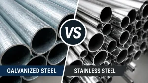
Common materials include galvanized steel, aluminum, and stainless steel. Galvanized steel is the standard choice for most commercial HVAC applications. Stainless steel or aluminum comes into play when corrosion resistance is the priority — kitchen exhaust, chemical plant ventilation, and similar environments.
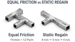
The practical advantage over rectangular ductwork is straightforward: round cross-sections have no sharp corners, so airflow transitions smoothly without turbulence buildup. Friction losses are lower, which translates directly into fan energy savings. Leakage rates are also lower because the sealing surfaces are simpler. If you’re choosing between the two for a new installation and space allows it, round ducting is the better engineering choice.
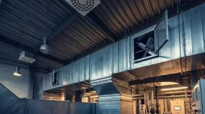
Typical applications include FCU supply and return air systems, industrial ventilation, exhaust systems in factories and commercial kitchens, and underground air distribution runs.

Example placement: “The quality of the duct itself starts at the manufacturing stage — a well-made spiral duct machine produces consistent seam geometry that directly affects installation fit and long-term leakage performance.”
2. Pre-Installation Preparation
Work on-site rarely goes wrong because of bad technique. Most problems trace back to preparation that was rushed or skipped. The steps below are not formalities — they determine whether the installation proceeds without interruption.
Material verification — Every duct section and fitting should arrive labeled with a tag number. Cross-check against the approved shop drawings before anything goes to the installation area. Check that all rubber gaskets are present and undamaged. A missing gasket on a coupling found mid-installation wastes more time than checking everything upfront.
Site readiness — Coordinate with other trades before starting. Duct supports cannot be placed until the ceiling structure is confirmed and other services (piping, cable trays) have been coordinated. Starting without this coordination means supports get repositioned later, which is avoidable rework.
Tools checklist:
- Portable grinding machine
- Drilling machine
- Sheet metal cutting tools
- Spirit level
- Scaffolding or elevated work platforms
- Rivet gun and self-tapping screws
- Air compressor and testing instruments
Safety briefing — Before work begins, the site supervisor should walk through height safety requirements (harness use, scaffolding inspection), PPE requirements for the specific tasks, and housekeeping expectations. Cut metal edges are sharp; gloves are not optional.

General Equipment
3. Duct Support Installation
Support positions are defined in the approved shop drawings. Do not improvise spacing based on convenience — support intervals are calculated against duct weight and pressure loads. Deviating from the drawings without engineering sign-off is not acceptable practice.
Mark support locations before drilling. Once the threaded rod positions are fixed, misaligned holes are difficult to correct cleanly.
Any cut edges on steel angles, channels, or threaded rods must be touched up with zinc-rich paint immediately after cutting. This is not a cosmetic step — unprotected cut edges corrode first, and in humid environments that corrosion spreads to the surrounding coating. Do it before installation, not after.
After supports are fixed, check alignment with a spirit level. Duct work runs that sag or twist between supports create drainage points for condensate and increase leakage risk at joints. Getting the supports level takes five minutes; correcting a sagging duct run after insulation is on takes much longer.

Duct hanger and layer
4. Duct Assembly and Jointing
Before assembling anything, inspect each duct section interior. Debris inside the duct at this stage becomes a contamination problem after the system is commissioned. Wipe down or blow out any dirt before joining sections.
Inspect rubber gaskets on every fitting before insertion. Damaged gaskets will leak regardless of how well the joint is mechanically secured. If a gasket shows cuts, deformation, or missing sections, replace it before proceeding.
Joint assembly procedure:
- Align the fitting with the duct end and push straight in until the fitting reaches its stop position.
- Slight rotation during insertion helps seat the fitting correctly — do not force it with lateral pressure, which risks gasket distortion.
- Once fully seated, secure with self-tapping screws or centered pop rivets distributed evenly around the circumference.
- Keep fasteners approximately 10mm back from the duct end and the fitting stop to avoid driving through the gasket.
- Any holes caused by incorrect fastener placement must be sealed — an unsealed hole defeats the entire leakage control effort.

pop rivets
5. Lifting and Aligning Duct Sections
Transport duct sections to the installation area only after confirming supports are fixed and checked. Moving duct prematurely leads to handling damage and congestion at the work face.
Raise each section onto supports and align with the preceding section before fastening. Use the approved shop drawings to confirm dimensions — do not eyeball alignment on long runs. Each section should be level with and axially aligned to its neighbor.
After installing each section, look inside before moving on. Tools, rags, offcuts — anything left inside will be sealed in once the run is closed off. It is easier to check at each joint than to investigate a restriction complaint after commissioning.
All open duct ends must be temporarily sealed with polyethylene sheeting or plywood at the end of each working day. This prevents moisture and construction dust from entering sections that have already been connected. Leaving ends open overnight is a common shortcut that creates problems during commissioning.
Accessories — volume control dampers (VCDs), test points, sensors — are installed in this phase, not retrofitted later. Confirm locations against approved drawings. A VCD installed in the wrong section is a significant rework item.
6. Duct Insulation Methods
Insulation is not just about thermal performance. In HVAC systems, inadequately insulated supply ductwork running through unconditioned spaces will sweat — condensate forms on the duct surface and drips, causing ceiling damage and mold growth. This section covers the standard insulation application for spiral round ducts using sheet insulation with adhesive bonding.
Surface preparation — The duct surface must be clean and completely dry before any adhesive is applied. Oil or grease contamination prevents bonding. Use solvent cleaner or thinner on contaminated areas and allow full evaporation before proceeding. Any rust spots should be addressed at this stage — adhesive will not hold over loose rust scale.
Adhesive application sequence:
- Apply adhesive evenly across the full surface of the insulation sheet.
- Allow the adhesive to reach tack — it should feel sticky but not transfer to a fingertip.
- Apply adhesive to the duct surface and allow it to reach the same tack condition.
- Start bonding from one end of the section. Press the insulation sheet onto the duct surface, working steadily from one end to the other to push out air pockets.
- Any air bubble trapped between the insulation and the duct surface creates a thermal bridge and a condensation risk point. Work systematically and press firmly.
Hanger contact points — Where the duct rests on hangers, there is a contact point between the metal support and the insulation. Direct contact causes abrasion and eventual tearing of the insulation facing as the duct vibrates during operation. The correct method:
- Glue a piece of timber onto the duct hanger.
- Apply a rubber layer between the timber and the insulation to prevent any direct hard contact.
- If the hanger position is known before insulation, the timber can be integrated into the support arrangement and insulation bonded to it from both sides.

Fire-rated penetrations — Where insulated ductwork passes through a fire-rated wall or partition, the annular gap between the duct sleeve and the surrounding structure must be filled with approved fire-stopping material. Standard insulation material is not a substitute. The fire-stopping specification is part of the building fire strategy and must match the approved submittal.
7. Conclusion
Spiral round ducting installation is a sequence of steps where each stage sets up the quality of the next. Support alignment determines duct alignment. Gasket condition at assembly determines leakage performance at testing. Insulation surface preparation determines long-term bond integrity. Cutting corners at any stage creates problems that compound downstream.
The material itself is reliable — spiral round ductwork has a long track record in commercial and industrial HVAC. Installation quality is the variable. Following the sequence documented here, with proper documentation at each IR stage, is how that quality gets locked in.
For projects requiring spiral round ductwork at scale, the consistency of the duct sections starts at the fabrication stage. Durmahvac’s spiral duct machines are built for commercial and industrial production environments — [contact our team] to discuss specifications for your project.
8. Quick Reference: Choosing the Right Gauge
Use this as a starting-point checklist before finalizing gauge specification for any duct run:
Step 1 — Identify duct type. Round spiral or rectangular? Round ducts can use thinner gauges at equivalent sizes due to structural geometry advantages.
Step 2 — Determine the largest duct dimension. For round ducts, use diameter. For rectangular, use the longest side. Match to the relevant size table.
Step 3 — Confirm the pressure class. Low, medium, or high pressure? Each tier above low pressure requires heavier gauge.
Step 4 — Check the material. Galvanized steel, aluminum, or stainless? Adjust gauge if substituting aluminum for steel.
Step 5 — Assess environmental and acoustic factors. Outdoor exposure, extended support spans, or noise-sensitive locations may justify stepping up one gauge beyond the table minimum.
Step 6 — Verify fabrication equipment capacity. Confirm that your cutting and forming equipment is rated for the gauge you’ve selected before beginning production.