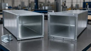
Rectangular ductwork is held together at every transverse joint by the same two-piece assembly that sheet-metal workers have relied on for generations: an S-cleat and a drive cleat. Understanding how each component functions — and how they depend on each other — is what separates a tight, leak-resistant connection from one that loosens under airflow or sags between hangers.
This guide covers the mechanics of the slip-and-drive joint, the structural profiles and gauge requirements of each component, a pre-installation checklist, a step-by-step field procedure, and the conditions that determine whether this joint type is appropriate for a given application.
All installation work should comply with the project drawings, applicable specifications, and the edition of SMACNA’s HVAC Duct Construction Standards — Metal and Flexible referenced in the contract documents. The procedures described here reflect typical practice and do not substitute for project-specific requirements.
1.What Is a Slip-and-Drive Duct Connection?
A slip-and-drive connection — also called an S-and-drive, S&D, S-lock-and-drive, or simply slip and drive in the field — is a transverse joint method used to connect two rectangular metal duct sections end to end. Rather than forming a continuous flange frame at the duct end, it uses two separately roll-formed sheet-metal components: the S-cleat and the drive cleat.
The S-cleat engages one pair of opposing duct edges to hold the sections aligned. The drive cleat captures the mated edges on the remaining two sides and locks the connection. Together, they form a complete mechanical joint around all four sides without bolts, welding, or separate corner hardware.
According to SMACNA, slip-and-drive is one of several recognized transverse joint types for rectangular duct. Its suitability for a specific installation — including permitted duct sizes, pressure classes, sheet-metal gauge, and reinforcement — is defined by the applicable construction tables in the project specification and governing standard, not by a general “low-pressure only” rule of thumb.
2. How the S-Cleat and Drive Cleat Work Together
The two cleats perform different mechanical functions. Neither one alone completes the joint.

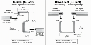
S-cleat — Roll-formed into an S-shaped cross-section, the S-cleat presents two opposing open channels. One channel receives the edge of the first duct section; the other captures the edge of the second. Once both edges are fully engaged, the S-cleat holds the two duct faces in plane and prevents lateral separation. It provides connection and alignment.
Drive cleat — Formed with an open channel (C-shaped) cross-section, the drive cleat fits over the mated hemmed or flanged edges of both duct sections simultaneously. It is slid progressively along those edges until fully seated. Because it is cut slightly longer than the duct side it covers, the protruding end material at each corner is bent over to lock the drive cleat in position. Those bent tabs also overlap the ends of the S-cleats, tying all four sides of the joint into a single locked unit.

2.1 S-Cleat and Drive Cleat Profiles and Gauge Requirements
Both components are typically roll-formed from galvanized steel sheet. The profiles and minimum material thickness are not arbitrary — SMACNA’s construction tables specify minimum cleat gauge as a function of the duct construction.
| Component | Cross-Section Profile | Primary Function | Typical Material |
|---|---|---|---|
| S-Cleat (S-Lock) | S-shaped, two opposing channels | Connects and aligns opposing duct edges | Galvanized steel sheet |
| Drive Cleat (C-Cleat) | Open C-channel | Locks mated hem edges; secured at corners by bent tabs | Galvanized steel sheet |
SMACNA’s published gauge requirements for flat slip and drive components (from the HVAC Duct Construction Standards — Metal and Flexible, Second Edition, 1995, Table referencing Figure 1-4 and associated notes) indicate minimum gauges of 24, 22, 20, or 18 ga depending on the pressure class and duct construction. The specific gauge requirement for a given project must be taken from the applicable construction table, not assumed from a general default.
The duct wall gauge is a separate specification from the cleat gauge. Both must comply with the construction tables for the designated pressure class and duct dimensions.
3. Before You Join the Duct Sections
A few minutes of checking before assembly prevents the most common installation problems: difficult fit, loose joints, edge damage, and sealant applied over a mechanically deficient joint.
Verify the project requirements. Confirm the specified joint type, duct material and wall gauge, pressure class, reinforcement requirements, seal class, and sealing method against the project drawings and specification before work begins. The joint designation, cleat gauge, and sealing obligation come from the construction tables, not from site habit.
Check the duct ends and edges. Both duct sections should have:
- Square, flat ends — no twist, bow, or racking that would prevent the cleats from seating flush
- Clean, undamaged mating edges and hems with no buckles, tears, or open seams near the joint
- Longitudinal seams fully closed and in good condition at the duct end
- No burrs or metal protrusions that would obstruct cleat insertion
A damaged hem or out-of-square end will make assembly difficult and may leave gaps that sealant cannot reliably bridge. Correct these conditions before attempting to join the sections.
Check the cleats. S-cleats and drive cleats should be:
- Straight along their full length, with no bow or twist
- Correctly profiled and gauged for the joint — the channels must fit the duct edge without binding or excessive play
- Cut to the required length; drive cleats are typically cut to leave enough material at each end for corner tabs as required by the joint detail
A cleat cut with offset snips will often have a small pinched tab at the cut end. Open this tab slightly with a flat tool or duct board knife before fitting; left closed, it will stop the cleat part way along the duct edge.
Prepare tools and PPE. A typical installation requires a rubber or wooden mallet, hand seamers, snips, and a flat tool for opening cleat ends. Sheet-metal edges are sharp; cut-resistant gloves and eye protection are required throughout. Support duct sections so they remain aligned during assembly — do not work over unsupported, suspended duct.
4. How to Install a Slip-and-Drive Joint
The following procedure reflects typical practice. Always follow the project specification and applicable SMACNA construction standard for the specific joint designation, duct size, and pressure class.
Step 1 — Support and align the duct sections. Position both sections so their ends are square to each other and fully supported. An unsupported section will shift during installation, making it difficult to seat the cleats correctly and introducing alignment errors into the finished joint.
Step 2 — Seat the S-cleats on the first duct section. Identify the two opposing edges that will receive S-cleats based on the project joint detail and the actual installed position of the duct. Slide one S-cleat onto each of those edges, working from one end to the other until the duct edge is fully engaged in one channel of the S.
The orientation matters. The S-cleat must be positioned so that the second duct section’s weight or load path bears on the duct metal, not on the cleat itself. A cleat carrying the suspended load will stretch open over time and loosen the connection — particularly on larger duct. Follow the joint detail for the correct orientation in the actual installed position; do not assume “top and bottom” if the duct is mounted differently.
Step 3 — Bring the second duct section into the S-cleats. Align the second section and slide its corresponding edges into the open channels of the seated S-cleats. Advance both ends evenly to keep the duct square. Confirm that both edges are fully and evenly engaged across the full length of each S-cleat before proceeding to the drive cleats.
Step 4 — Install the drive cleats. Position a drive cleat over the mated hemmed edges on one of the remaining sides. Starting from one end, advance the cleat along the edges using even, controlled mallet strikes. Work progressively — do not concentrate force in one spot, as that will deform the duct edge or open the hem. The cleat should travel smoothly and remain perpendicular to the duct end.
Repeat on the opposite side.
Step 5 — Secure the corner tabs. Once each drive cleat is fully seated, fold the protruding end material at both corners over the duct face using hand seamers or a bending tool. This locks the drive cleat in position and, where the tab overlaps the end of an S-cleat, ties the S-cleat in place as well.

The required tab length and fold method depend on the joint configuration and project detail. Do not prescribe a fixed dimension independently of those requirements.
Step 6 — Seal the joint. Apply the sealant type and coverage specified in the project documents. SMACNA’s standard sealing requirements (Table 1-2) are based on static pressure class:
| SMACNA Seal Class | Applies To | Sealing Required |
|---|---|---|
| C | Transverse joints only | 2 in. w.g. (500 Pa) pressure class |
| B | All transverse joints and longitudinal seams | 3 in. w.g. (750 Pa) pressure class |
| A | All transverse joints, seams, and duct wall penetrations | 4 in. w.g. (1000 Pa) and above |
Note that SMACNA also recommends Seal Class C for 1 in. w.g. and ½ in. w.g. pressure class ducts when specified by the designer — the standard does not mandate sealing at those levels by default, but it is recommended practice and many project specifications require it.
Areas that consistently require attention during sealing:
- All four corners, where S-cleat and drive cleat ends meet — these are the most common leakage points
- The full length of each cleat-to-duct interface, particularly where the duct edge sits inside the S-cleat channel
- Any other interfaces defined in the project sealing requirements
Sealant applied over gaps from a poorly assembled joint will not maintain airtightness reliably. Complete the mechanical assembly before sealing.
5. Inspect the Joint and Correct Common Problems
After assembly, a brief visual check confirms the joint is mechanically complete before it moves or is concealed.
What to verify:
- Duct sections are aligned and square at the joint with no visible offset between faces
- S-cleats are fully engaged — no duct edge has backed out of a channel
- Drive cleats are fully seated end to end, not riding up or tilting
- Corner tabs are folded tightly against the duct surface on all four corners
- Sealant is continuous and covers all required interfaces with no dry gaps at corners or cleat ends
- No duct edges have buckled or lost their galvanized coating from excessive force
Common problems and their causes:
| Symptom | Likely Cause | Action |
|---|---|---|
| Drive cleat difficult to advance | Duct ends not square; edges too wide; cleat profile too tight | Check squareness and edge alignment before applying more force |
| Drive cleat rides up or tilts | Hemmed edges not parallel; one edge higher than the other | Realign duct sections; verify hem consistency |
| S-cleat slips or backs out | Duct edge not fully engaging channel; channel stretched from incorrect load orientation | Reseat cleat; verify orientation matches the joint detail |
| Gap visible at corner | Drive tab not folded tightly; cleat ends misaligned | Refold tabs cleanly; apply specified sealant |
| Duct edge buckled or coating damaged | Force concentrated in one area; cleat driven over a distorted edge | Stop; assess whether the edge or cleat requires replacement |
Do not use sealant to cover a joint that did not assemble correctly. Address the mechanical fit first.
On duct support: a slip-and-drive connection is a transverse joint — it carries no hanger load. Duct sections must be independently supported at the spacing and method required by the project drawings and applicable SMACNA hanger tables. A joint asked to carry weight it was not designed for will work loose regardless of assembly quality.
6. Where Slip-and-Drive Is Appropriate — and When to Confirm Another Joint Type
Slip-and-drive is a recognized transverse joint type in SMACNA’s rectangular duct construction standards and is used extensively across commercial and residential HVAC installations. That broad use does not mean it is universally appropriate.
SMACNA is explicit: “The terms ‘low’ and ‘high’ as applied to velocity and pressure are vague and are no longer used. The designer must select a numerical static pressure class.” A joint designated as suitable for one pressure class is not automatically permitted at a higher one, and the duct size affects both wall gauge and reinforcement requirements independently of the joint type.
The factors that determine whether slip-and-drive is correct for a specific duct section:
| Factor | What Must Be Verified |
|---|---|
| Duct dimensions | Maximum permitted duct dimension for the selected joint type at the specified pressure class |
| Pressure class | Whether the joint is listed as acceptable at the specified positive or negative pressure class in the applicable SMACNA table |
| Sheet-metal gauge | Minimum required wall gauge and cleat gauge for the duct size and pressure class |
| Reinforcement | Whether intermediate reinforcement is required between joints for the specified duct width and pressure class |
| Seal class | The required seal class (A, B, or C) derived from the static pressure class per SMACNA Table 1-2 or the project specification |
If the design requires greater joint rigidity, a higher pressure capability, or a more standardized sealing surface — such as a TDC or TDF flange connection — confirm the specified joint type with the project engineer before fabricating or installing. Substituting a slip-and-drive joint where a flanged connection is specified affects structural performance, airtightness, and project compliance. It is not a field substitution to make on the basis of convenience.
For background on SMACNA’s construction tables and pressure classification framework, refer to HVAC Duct Construction Standards — Metal and Flexible (SMACNA) and the ASHRAE Handbook — Fundamentals, Chapter on duct design.
7. FAQ
Answer: They serve different mechanical roles. The S-cleat has an S-shaped cross-section with two opposing channels; it slides over one pair of opposing duct edges to hold the two sections in alignment. The drive cleat has an open C-channel profile; it is driven over the mated hemmed edges on the other two sides to lock the connection. The drive cleat’s end tabs are then bent over at the corners to secure the assembly. Neither component functions correctly without the other.
Answer: No. The mechanical assembly provides structural connection, but the joint contains several interfaces — corner intersections, cleat-to-duct edges, and the channel interiors — through which air can leak. SMACNA’s seal class requirements (Table 1-2) define what sealing is required based on the static pressure class. At 2 in. w.g. and above, transverse joints must be sealed; at higher pressures, longitudinal seams and duct wall penetrations are also included. For 1 in. w.g. and ½ in. w.g. systems, sealing at transverse joints is recommended and is typically required by project specifications even where the standard does not mandate it.
Answer: Yes, and it is a common source of loose joints. The S-cleat must be oriented so that the load path of the suspended duct section bears on the duct metal — not on the cleat channel. A cleat carrying the weight of the second duct section will gradually stretch open and loosen. The correct orientation depends on the actual installed position of the duct and the joint detail, not on a fixed “top and bottom” rule that may not apply when the duct is rotated or mounted in an unusual orientation.
Answer: Rarely. Removing a drive cleat typically requires bending back the locked corner tabs, which deforms the cleat and shortens it. A shortened cleat will not cover the same duct dimension and usually cannot be reformed to its original profile. S-cleats are more recoverable — if removed carefully and remaining straight and undamaged, they can generally be reused. For most rework and demolition scenarios, using new cleats is the more reliable approach.
Answer: Check the project specification and applicable SMACNA construction table for the designated pressure class and duct dimensions. Slip-and-drive (flat slip and drive) is listed as a recognized joint type in SMACNA’s tables and is used across a range of applications, but maximum permitted duct dimensions, minimum cleat gauge, and reinforcement requirements all vary by pressure class. If the project does not specify the joint type, the default pressure class under SMACNA is 1 in. w.g. where no class is designated. When in doubt, confirm the joint designation with the project engineer before fabrication.
8. Conclusion
A slip-and-drive joint works because two simple components do two clearly defined jobs — alignment and locking — and the corner tabs tie them together. When the duct ends are square, the cleats are correctly profiled and oriented, the drive cleats are advanced evenly, and the sealing follows the project’s specified seal class, the result is a mechanically stable, airtight joint that has held ductwork together across countless HVAC installations.
The most persistent field problems — loose connections, air leaks, difficult assembly — trace back to conditions that existed before the first cleat was installed. Checking duct-end condition and cleat fit before assembly is not cautious; it is efficient, because fixing a poor joint after the fact costs more than preventing it.
Before starting a new duct run, verify the joint type in the project documents. When a project specifies a flanged connection, that choice reflects a structural and airtightness requirement — not a preference that can be overridden on the job site with a more familiar method.