

1. Introduction
An HVAC system can only deliver what its ductwork allows through. You can install the most efficient compressor on the market, but if the air has to fight its way through undersized trunks, sharp elbows, and leaky joints to get there, the system will never perform to its rated specification. Ductwork is the delivery infrastructure of climate control — and like any infrastructure, its design determines whether the system underneath it succeeds or struggles.
This guide breaks down what ductwork actually is, the seven design variables that govern airflow performance, and how to recognize — and correct — a duct system that isn’t pulling its weight.
2. What Is HVAC Ductwork?
HVAC ductwork is the network of enclosed passages — typically formed from galvanized steel, aluminum, or fiberglass duct board — that carries conditioned air between the air handling unit and the occupied spaces of a building. It operates in two directions: supply ducts push heated or cooled air out to rooms, while return ducts pull interior air back to the unit for reconditioning and filtration.
The physics involved are not complicated in principle: air moves from high pressure to low pressure, and a blower fan supplies the pressure difference needed to move it. But the moment that air enters a duct, every geometric decision — the shape of the cross-section, the smoothness of the interior surface, the number of turns it has to make — either helps that air travel efficiently or works against it. Duct design is the discipline of managing that resistance so the system delivers its rated airflow with minimum wasted energy.
3. The Seven Factors That Determine Duct Airflow Performance
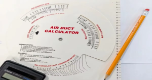
Engineers size and route ductwork against a defined CFM (cubic feet per minute) target for each room, calculated from square footage, occupancy, and heating/cooling load — typically following an ACCA Manual D calculation. Once that target is set, seven physical factors determine whether the duct can actually deliver it.
| Factor | What It Controls | Design Impact |
|---|---|---|
| Duct Shape | Airflow pattern and friction | Round ducts produce the most laminar, low-friction flow; rectangular ducts trade some efficiency for space-fitting flexibility |
| Duct Size | Air velocity and CFM capacity | Undersized ducts restrict flow and raise noise; oversized ducts drop velocity and cause uneven distribution |
| Fittings (elbows, transitions) | Turbulence and local resistance | Each fitting adds resistance equivalent to several feet of straight duct — fewer, gentler fittings perform better |
| Duct Length | Cumulative static pressure loss | Every additional meter of run adds friction; long branches need larger diameters to compensate |
| Duct Material | Interior surface friction | Smooth rigid metal outperforms flexible duct, which has a corrugated interior that multiplies resistance |
| Duct Routing | Total pressure loss and thermal exposure | Short, direct paths through conditioned space reduce both friction loss and energy loss to ambient temperature |
| Code Compliance (SMACNA, IMC, local amendments) | Minimum sizing, sealing class, and material standards | Meeting or exceeding code thresholds prevents both performance failures and inspection issues |
Duct sizing software — Manual D-compliant tools, or CAD platforms such as Autodesk Revit for larger commercial projects — models these seven variables together, since changing one (say, switching from round to rectangular ducts in a tight ceiling cavity) shifts the required size and routing of everything downstream.
4. How These Factors Actually Play Out in a Working System
4.1 Sizing Errors Compound in Both Directions
Undersized ductwork is the most common airflow complaint, and the mechanism is straightforward: force the same CFM through a smaller cross-section, and velocity — along with friction and noise — rises sharply. The blower has to work harder to push against that resistance, energy consumption climbs, and the system may never reach its rated static pressure at all.
Oversized ductwork causes a quieter but equally real problem. Air velocity drops, which sounds harmless until you realize that low velocity means poor air mixing at the register and weaker distribution to rooms further down the run. Some oversized systems also develop condensation on interior duct surfaces, since slow-moving air has more time to lose heat to a cooler duct wall.
Getting sizing right isn’t a matter of “bigger is safer.” It’s matching cross-sectional area precisely to the CFM the room requires — no more, no less.
4.2 Layout Geometry Sets the Resistance Floor
A duct system’s total resistance is set the moment its layout is drawn, before a single panel is fabricated. Straight, well-insulated runs move air with minimal turbulence. Runs with unnecessary elbows, tight offsets, or kinked flexible sections force air to constantly change direction and speed, and every one of those changes bleeds static pressure.
Register and return placement matters just as much as the duct path itself. A return grille positioned too close to a supply register short-circuits airflow — conditioned air gets pulled back into the system before it ever mixes into the room. Balanced layouts route supply and return points to opposite ends of a space, so air is forced to travel through — and actually condition — the full room.
4.3 Leakage Silently Erodes Everything Upstream
Even a well-sized, well-routed duct system underperforms if its joints aren’t sealed. Industry field studies commonly cite conditioned-air losses of 20–30% through unsealed ductwork in older or poorly fabricated systems — air that the blower already spent energy moving, lost before it reaches a single room. Leakage also distorts diagnosis: a system reading low static pressure might not be oversized at all — it might simply be leaking air out before the pressure ever registers downstream.
Mastic sealant and UL 181-rated foil tape at every joint and seam are the baseline standard; ordinary cloth-backed duct tape dries out and fails within months under normal thermal cycling.
5. Signs Your Ductwork Design Needs Attention
A duct system rarely announces its problems outright — it degrades gradually, and the symptoms are easy to blame on the equipment instead of the delivery system underneath it. Watch for:
- Noticeable temperature differences between rooms served by the same system
- Weak or barely-detectable airflow from vents at the end of a duct run
- Rising energy bills without a corresponding increase in usage or outdoor temperature extremes
- Whistling, rattling, or rushing noise from vents and duct joints
- Visible dust accumulation around registers, or a sudden increase in indoor dust
- Condensation, staining, or musty odor near duct sections in unconditioned spaces
Any one of these on its own could point elsewhere, but two or more together are a strong signal that the ductwork — not the equipment — is the bottleneck.
6. How to Correct and Optimize an Underperforming Duct System
- Seal every accessible joint and seam with mastic or UL 181 foil tape, and run a duct leakage test to confirm the fix held
- Add or upgrade insulation on runs passing through attics, crawl spaces, or unconditioned zones (R-6 to R-8 is the common baseline)
- Replace crushed, kinked, or disconnected sections, particularly in flexible duct, where physical damage is easy to miss during a casual inspection
- Rebalance duct sizes and branch routing against an updated Manual D calculation if the building’s load profile has changed
- Favor round or oval cross-sections over sharp-cornered rectangular runs wherever the ceiling or wall cavity allows it
- Shorten and straighten routing where possible — every eliminated bend is resistance the blower no longer has to overcome
- Have ducts professionally cleaned if dust accumulation has become a persistent issue, particularly in systems that haven’t been serviced in several years
None of these fixes work in isolation for long. A resized trunk feeding into leaky branch ducts still loses air; sealed joints on an undersized system still choke on velocity. Diagnosing the actual bottleneck — with a static pressure reading and a visual inspection — should always come before deciding which fix to apply
7. Design Standards That Keep Ductwork Accountable
Duct design isn’t governed by intuition — it follows published, testable standards, and citing them is what separates a properly engineered system from a guess:
- ACCA Manual D — the accepted method for calculating duct sizes based on room-by-room load and airflow requirements
- ACCA Manual J — the load calculation that Manual D depends on; sizing ducts without a current Manual J is sizing against the wrong number
- SMACNA HVAC Duct Construction Standards — governs sheet metal gauge, reinforcement, sealing class, and pressure classification for fabricated ductwork
- International Mechanical Code (IMC) and local amendments — set minimum legal requirements for material, clearance, and fire-rated penetrations
Ductwork that is fabricated to hold tight dimensional tolerances — consistent seam quality, accurate gauge, true-round or true-rectangular cross-sections — gives every design calculation upstream a fighting chance of translating into real-world performance. Ductwork fabricated with loose tolerances introduces friction losses and leak points that no amount of correct sizing can fully offset.
8. FAQ
Supply ducts carry conditioned air from the air handler out to rooms; return ducts pull room air back to the unit for filtering and reconditioning. A system needs both operating in balance — a supply-heavy, return-starved system will struggle to maintain static pressure regardless of how well the supply side is sized.
For airflow efficiency alone, yes — round cross-sections have no corners to generate turbulence, so they move a given CFM with less friction and less material. Rectangular ducts remain common because they fit into shallow joist bays and tight ceiling spaces where a round duct’s diameter simply won’t fit.
Measure static pressure at the supply and return with a manometer and compare the total against the air handler’s rated external static pressure on its data plate. Readings consistently above that rating point to duct-side restriction — the equipment is fine, but the duct isn’t letting it breathe.
Yes, meaningfully. Since ductwork commonly accounts for a large share of an HVAC system’s total energy loss through leakage and friction, sealing, correct sizing, and reduced fitting count can lower run time and energy consumption without touching the equipment itself.
No — flexible duct’s corrugated interior surface generates significantly more friction per foot than smooth rigid metal, and sagging or kinked flex sections make the difference worse. It remains useful for short connector runs, but long, sagging flex runs are one of the most common preventable sources of airflow loss.
9. Conclusion
Ductwork is not a passive pipe system — it’s an active variable in every HVAC system’s performance. Shape, size, fittings, length, material, routing, and code compliance interact to either support or undermine the equipment they’re connected to. Getting the design right starts with correct load calculations and ends with fabrication precision that holds those calculations true in the field.
For fabricators building rectangular, spiral, or round ductwork to those specifications, Durmahvac’s auto duct production lines and spiral duct machines are engineered to hold the dimensional tolerances that well-designed duct systems depend on — because a design is only as good as the ductwork that carries it out.