1.Introduction
An HVAC duct sizing chart converts a system’s airflow requirement—measured in cubic feet per minute (CFM)—into the exact round diameter or rectangular dimensions an installation requires. Sized correctly against the standard friction loss rate of 0.1 inches of water column (in. w.c.) per 100 feet, ductwork delivers efficient, quiet, balanced airflow to every room.
Sized incorrectly, ductwork can significantly increase static pressure, reduce system efficiency, and force HVAC equipment to operate under higher load conditions—leading to noise, uneven temperatures, and premature equipment strain. This guide combines standard chart data (Southwark Metal reference tables), ACCA Manual D design principles, and ASHRAE velocity guidance so you can size any residential or light-commercial system with confidence.
Quick Answer To size a duct:
(1) find the room’s required CFM from a Manual J load calculation,
(2) select a friction rate (0.1″ w.c./100 ft for rigid metal),
(3) look up the CFM in the chart to read the round diameter or rectangular equivalent
(4) verify velocity is within target. Always upsize flex duct by 1–2 inches and account for fitting equivalent length before finalizing.
2.Quick Reference: HVAC Duct Sizing Chart (0.1″ Friction Loss)
Find your required CFM, then read across for the round diameter, rectangular equivalents, and the resulting air velocity. Values are based on the industry-standard 0.1″ w.c./100 ft friction rate for rigid metal ductwork.
| Airflow (CFM) | Round Diameter (in) | Common Rectangular Options (in) | Approx. Velocity (FPM) | Typical Application |
|---|---|---|---|---|
| 50 | 5" | 6×4, 8×6 | ~367 | Small bedroom register |
| 100 | 6" | 8×6, 10×4 | ~509 | Bedroom / bathroom |
| 150 | 7" | 8×6, 10×4 | ~561 | Standard bedroom |
| 200 | 8" | 8×6, 14×4 | ~573 | Large bedroom / small office |
| 300 | 9" | 8×8, 12×6 | ~679 | Dining room / medium office |
| 400 | 10" | 10×8, 14×6 | ~733 | Living room / open zone |
| 600 | 12" | 12×10, 14×8, 20×6 | ~764 | Large open-plan space |
| 800 | 14" | 14×10, 18×8 | ~748 | Light commercial / main trunk |
| 1,000 | 16" | 16×10, 22×8 | ~716 | Main trunk duct |
| 1,500 | 18" | 24×10, 20×12 | ~849 | Large supply trunk |
| 2,000 | 20" | 24×10, 24×14 | ~917 | Large residential / small commercial AHU |
Data compiled from standard residential 0.10″ sizing charts (Southwark Metal reference data). See References.
3.How to Calculate Duct Size from CFM
A chart is fast, but understanding the underlying formula lets you size any airflow and cross-check the chart against your own velocity target.
3.1 The Round Duct Sizing Formula
To find the round duct diameter (in inches) from airflow and target velocity:
Where:
- D = duct diameter (inches)
- CFM = required airflow
- V = target air velocity (FPM)
This matches the chart’s 10″ recommendation for 400 CFM—confirming the two methods agree.
3.2 Simple CFM-to-Duct-Size Calculator (Round, 0.1″ Friction)
If you prefer a lookup over the formula, use these common design points:
| Input CFM | Target Velocity (FPM) | Recommended Round Size |
|---|---|---|
| 100 | ~500 | 6" |
| 200 | ~575 | 8" |
| 300 | ~680 | 9" |
| 400 | ~730 | 10" |
| 600 | ~765 | 12" |
| 1,000 | ~715 | 16" |
3.3 Field Example: Sizing a Bedroom Supply Duct
A bedroom requires 120 CFM of supply air. Assuming a 0.1″ w.c./100 ft friction rate, rigid metal duct, and a 600–900 FPM velocity target:
- The chart shows a 6-inch round duct carries roughly 100 CFM.
- Because the actual requirement is 120 CFM, a 7-inch round duct is the safer selection—especially once fitting losses on the run are considered.
This is the kind of judgment call the chart alone won’t make for you: when the requirement falls between two rows, round up, then verify velocity stays in range.
4. The Three Core Principles Behind Every Duct Sizing Chart
Change one of these three interdependent variables and the other two shift with it.
1. Airflow Volume (CFM): Where Every Decision Starts
CFM must come from a formal ACCA Manual J load calculation accounting for room size, insulation, glazing, occupancy, and climate. The “1 CFM per square foot” shortcut is a rough sanity check only—never a final design value.
2. Friction Loss Rate: Understanding the “0.1 Standard”
Friction loss is the pressure drop air experiences along duct walls and through fittings. Most charts standardize on 0.1″, reliable for typical rigid metal systems. Long runs with many fittings or extensive flex duct warrant a more conservative 0.08″ to protect airflow at remote registers.
3. Air Velocity (FPM): Balancing Efficiency Against Noise
Too slow, and air never reaches distant rooms; too fast, and you get noise plus excessive static pressure. Cross-check every chart result against these ASHRAE velocity targets:
| Duct Type | Target Velocity (FPM) | If Exceeded |
|---|---|---|
| Residential Supply | 600–900 | Audible whooshing at registers |
| Residential Return | 500–700 | Noise at grilles |
| Branch / Room Duct | 400–600 | Register noise and drafts |
| Commercial Supply | 800–1,500 | Higher noise tolerance by design |
4. The Three Core Principles Behind Every Duct Sizing Chart
Change one of these three interdependent variables and the other two shift with it.
1. Airflow Volume (CFM): Where Every Decision Starts
CFM must come from a formal ACCA Manual J load calculation accounting for room size, insulation, glazing, occupancy, and climate. The “1 CFM per square foot” shortcut is a rough sanity check only—never a final design value.
2. Friction Loss Rate: Understanding the “0.1 Standard”
Friction loss is the pressure drop air experiences along duct walls and through fittings. Most charts standardize on 0.1″, reliable for typical rigid metal systems. Long runs with many fittings or extensive flex duct warrant a more conservative 0.08″ to protect airflow at remote registers.
3. Air Velocity (FPM): Balancing Efficiency Against Noise
Too slow, and air never reaches distant rooms; too fast, and you get noise plus excessive static pressure. Cross-check every chart result against these ASHRAE velocity targets:
5. Flex Duct vs. Rigid Metal: The Material Correction
The interior surface roughness of a duct changes its friction loss, which is why professionals adjust the friction setting on their ductulator based on the product being installed.
5.1 Typical Reference Friction Values by Material
Typical design friction rates may vary depending on duct material, system design, and manufacturer recommendations. The values below are common ductulator reference settings, not fixed material constants:
| Duct Material | Typical Reference Value | Relative Resistance |
|---|---|---|
| Flexible Duct (Flex) | ~.05" | Highest (corrugated interior) |
| Round Metal Pipe | ~.06" | Moderate |
| Rectangular Sheet Metal | ~.07" | Lowest (smooth walls) |
5.2 Why Flex Duct Must Be “Sized Up”
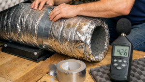
Flex duct’s corrugated interior creates far more turbulence than smooth metal. To move the same CFM as rigid duct, upsize flex by 1–2 inches in diameter—where a rigid chart calls for 8″, install 9–10″ flex. Always pull flex duct completely taut; a compressed or sagging run can substantially increase friction loss and negate correct sizing.
[Suggested image: side-by-side “Before / After” — a loose, sagging flex run vs. a properly stretched and supported run. Strong visual EEAT signal for a physically-installed product.]
6. Total Effective Length (TEL): The Hidden Resistance in Fittings
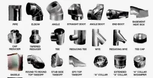
The most common and costly sizing mistake is sizing a run on straight linear feet alone. Every elbow, boot, and takeoff adds “equivalent length” (EL)—an imaginary length of straight duct that produces the same resistance.
6.1 Representative Fitting Equivalent Lengths
| Fitting | Equivalent Length (EL) |
|---|---|
| 90° Round Elbow | 30 ft |
| 45° Angle | 10–20 ft |
| Radius-Throat Duct Elbow (up to 11") | 10 ft |
| Square-Throat Duct Elbow (up to 11") | 40 ft |
| Square-Throat Duct Elbow (22"–27") | 100 ft |
| Cold-Air Return Boot (No. 810) | 45–65 ft |
Data from the Southwark Metal Duct School Reference Guide.
6.2 Worked Example: How Fittings Inflate a Run
Consider a supply run with 30 ft of straight duct and two square-throat elbows:
- Straight duct: 30 ft
- Two square-throat elbows (≈40 ft each): 80 ft
- Total Effective Length: 110 ft
The fittings contribute nearly 3× the resistance of the straight duct. Sizing this run as if it were only 30 ft would starve the remote register. Swapping to radius-throat elbows (≈10 ft each) would cut the TEL from 110 ft to just 50 ft—often the difference between adequate airflow and a chronic callback.
6.3 The Quick Field Fix
If a run includes more than two or three sharp turns, increase that section by one size above the chart value to compensate for fitting friction without a full recalculation on-site.
7.Special Cases: Tight Spaces and High Altitude
7.1 Narrow “Wall Stack” Ducts for Space-Constrained Runs
Retrofits and interior-wall runs often can’t fit a standard duct depth. Narrow profiles keep the required CFM moving through a shallow cavity:
| Narrow Duct Size | Approx. Airflow |
|---|---|
| 2½ × 10 | ~40 CFM |
| 2½ × 14 | ~70 CFM |
| 3½ × 14 | ~100 CFM |
7.2 Altitude Correction Factor (ACF)
Air is thinner at elevation, so the same duct delivers less capacity. Apply the ACF to your CFM calculations:
| Altitude | ACF | Altitude | ACF |
|---|---|---|---|
| 0 ft | 1.00 | 5,000 ft | .826 |
| 1,000 ft | .962 | 7,000 ft | .772 |
| 3,000 ft | .891 | 10,000 ft | .687 |
At 5,000 ft you need roughly 20% more airflow to move the same amount of heat—an easily overlooked factor behind chronic under-performance in mountain-region installs.
8. The Four Most Costly Duct Sizing Mistakes
1. Undersizing the Return Air Duct
An undersized return starves the air handler. The blower strains and the result can be a frozen evaporator coil in cooling or an overheated heat exchanger in heating—both warranty-voiding failures. Size returns to match total system CFM at 500–700 FPM, and keep return CFM ≥ supply CFM.
2. Ignoring Fitting Resistance
As the TEL example shows, fittings can outweigh straight duct entirely. Total your equivalent length before finalizing sizes.
3. Installing Flex Duct Loose or Compressed
Correct sizing means nothing if flex duct sags. Pull every run taut and support it properly.
4. Connecting a Takeoff at the End of the Trunk
The last takeoff should never sit at a trunk’s dead end, where static pressure is lowest. Reduce trunk size progressively after each branch to maintain velocity.
9. How Proper Duct Sizing Helps Duct Manufacturers
Accurate sizing isn’t only a field concern—it drives fabrication efficiency upstream. When duct dimensions are specified correctly and consistently, manufacturers benefit directly:
- Reduced material waste: Right-sized, standardized dimensions minimize offcuts and re-runs of coil stock.
- Improved fabrication consistency: Clean size schedules let production lines batch identical profiles instead of one-off custom pieces.
- Less rework: Correct sizing at design time prevents mismatched fittings and on-site returns that stall a project.
- Faster throughput: Predictable size distributions keep spiral and rectangular lines running with fewer changeovers.
For shops scaling production, the sizing discipline above pairs naturally with the right equipment—spiral duct forming machines, rectangular duct production lines, and auto duct fabrication lines that turn accurate size schedules into consistent, low-waste output.
(Replace the placeholder links with the corresponding product/category pages.)
10.FAQ
At a standard 0.1″ friction rate, 400 CFM requires a 10-inch round duct or a rectangular equivalent such as 10×8 or 14×6. For flexible duct, upsize to 11–12 inches to compensate for corrugation friction.
A 6-inch round metal duct carries roughly 100 CFM at a typical residential velocity (~500 FPM) and 0.1″ friction. A 6-inch flex duct handles slightly less due to higher internal friction.
Yes. Size flexible duct 1–2 inches larger in diameter than the rigid equivalent for the same CFM, and always pull it taut—a compressed section significantly increases friction loss.
0.1″ w.c. per 100 ft is the industry standard for residential and light-commercial rigid metal ductwork. Use the more conservative 0.08″ for long runs, many fittings, or extensive flex duct.
11. Conclusion
- Calculate room-by-room CFM with ACCA Manual J.
- Select the correct friction rate for your material (0.1″ metal; adjust for flex).
- Read the chart—or apply the formula—for round diameter or rectangular equivalent.
- Add the equivalent length of every fitting to find TEL.
- Correct for flex duct and altitude where applicable.
- Verify velocity is within ASHRAE targets, and confirm the return matches the supply.
Follow this loop, back it with reliable chart data, and you’ll deliver systems that run quietly, efficiently, and complaint-free for their service life.