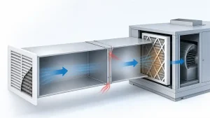

HVAC duct fittings connect, redirect, branch, reduce, and terminate duct runs. Common types include elbows, tees, wyes, reducers, transitions, takeoffs, boots, couplings, and end caps.
The right fitting affects airflow, pressure loss, leakage, noise, installation space, and maintenance access. This guide explains the main duct fitting types, their uses, how to select the correct fitting for each application, and what to include when ordering standard or custom components.
[Image: Isometric cutaway diagram of a commercial HVAC duct system with labeled fittings including elbows, wyes, reducers, register boots, and couplings] [Image Prompt: Isometric technical illustration of a commercial HVAC ductwork system. Main rectangular trunk duct branches into round spiral sub-ducts. Clearly labeled components: long-radius elbow, wye branch, concentric reducer, register boots, flanged coupling. Clean white background, blue and gray color scheme, professional engineering diagram style, callout labels only, no decorative text.] [Alt Text: Isometric diagram of commercial HVAC ductwork with labeled fittings including elbows, wyes, reducers, and register boots]
1. What Are HVAC Duct Fittings?
A duct fitting is any component in a ductwork system that is not a plain straight section. Fittings change direction, split or combine airflow, step between sizes or shapes, connect duct sections, join ductwork to equipment, or terminate unused branches.
Straight sections carry air with predictable frictional resistance. Fittings create dynamic pressure losses that depend on geometry — the angle of a turn, the abruptness of a branch, the ratio of inlet to outlet area. Those losses accumulate across every fitting in the system and directly affect available static pressure at each terminal device. Every fitting joint is also a potential leak point; connection type, sealing method, and installation quality determine whether the system holds pressure or bleeds air into the ceiling plenum.
2. HVAC Duct Fittings at a Glance
| Fitting Type | Primary Function | Common Applications | Key Selection Detail |
|---|---|---|---|
| Elbow / Bend | Change duct direction | All duct systems | Long-radius preferred; short-radius where space is limited |
| Offset | Navigate around obstructions | All systems | Define drop, rise, and travel dimensions precisely |
| Tee | 90° branch connection | Return air, low-velocity runs | Higher pressure loss than wye; use where space limits angle |
| Wye / Lateral | Angled branch connection | Supply air distribution | Preferred over tee for supply runs |
| Takeoff / Start collar | Connect branch to trunk | Round and flat-oval trunks | Conical entry preferred over straight tap |
| Reducer | Change duct diameter | Transitions between duct sizes | Concentric or eccentric depending on orientation |
| Transition | Change duct shape or size | Equipment connections, mixed systems | Keep included angle moderate to limit losses |
| Coupling | Straight connection | Round and spiral duct | Match duct OD and connection system |
| Flange / Cleat | Bolted or cleat joint | Rectangular duct | Match pressure class requirements |
| Collar / Boot | Terminal or equipment interface | Branch starts, register connections | Coordinate with device neck dimensions |
| End Cap / Plug | Seal unused openings | Capped branches, test ports | Confirm pressure class and sealing method |
| Access Fitting | Inspection, cleaning, service | Near dampers, filters, sensors | Ensure clearance for door swing and service tool |
3. Types of HVAC Duct Fittings and Their Uses
3.1 Elbows, Bends, and Offsets
Elbows redirect duct runs around structural elements, align ductwork with equipment connections, and navigate constrained ceiling spaces. They are among the most common fittings and a significant source of fitting-related pressure loss when selected or installed poorly.
The two most common elbow angles are 90 degrees and 45 degrees. Within 90-degree configurations, the centerline radius determines how smoothly air navigates the turn:
- Long-radius elbows — centerline radius approximately 1.5 times the duct diameter — allow air to follow the curve with less separation and are preferred where space allows
- Short-radius elbows are more compact but create a sharper turn that increases turbulence
- Segmented elbows (common in spiral duct) are assembled from angled sections; the number of segments affects both the smoothness of the airflow path and installed length
- Mitered elbows — used in rectangular duct where curved profiles are impractical — generally produce higher pressure losses than smooth-radius configurations; internal turning vanes substantially reduce that loss and are required by many project specifications in higher-velocity applications
Where routing permits, two 45-degree elbows with a short connecting section often produce less combined turbulence than a single 90-degree fitting. Offsets use two bends to shift a duct run laterally or vertically around a beam, pipe, or cable tray; a moderate bend angle at each end reduces flow disturbance compared to steep, short offsets.
3.2 Tees, Wyes, Laterals, and Takeoffs
Branch fittings divide supply air or combine return air at junction points. The branch geometry directly affects how evenly airflow distributes and how much static pressure is lost at the junction.
| Fitting | Branch angle | Typical use | Flow characteristic |
|---|---|---|---|
| Tee | 90° perpendicular | Return air, low-velocity branches | Air must make a sharp turn; higher pressure loss |
| Wye / Lateral | 30–45° in direction of flow | Supply air distribution | Smoother branch entry; lower pressure loss than tee |
| Conical takeoff | Tapered angled entry | Round/flat-oval trunk to branch | Improved branch flow extraction vs straight tap |
| Saddle tap | Field-installed, no trunk disassembly | Retrofit branch additions | Faster installation; requires careful field sealing |
| Start collar | Welded or riveted to trunk | Round branch starts | Standard branch connection on fabricated systems |
For supply-air distribution, wyes are generally preferred over tees because the angled branch entry allows smoother flow division and typically requires fewer balancing adjustments. Tees are acceptable in return-air applications at lower velocities, or where physical space prevents the use of an angled fitting. Where the airflow split between branches must meet a precise design value, a balancing damper in the branch run provides the adjustment capability that fitting geometry alone cannot guarantee.
3.3 Reducers and Transitions
Reducers change duct diameter while keeping the same cross-sectional shape. Transitions change the shape — for example, from round to rectangular — or both shape and size simultaneously. Both should be designed with a gradual taper; an abrupt change in cross-section creates turbulence, noise, and higher pressure loss.
Within reducers, two configurations handle different installation conditions:
- Concentric reducer — inlet and outlet centerlines aligned; suitable for vertical runs and equipment connections where centering is the relevant reference
- Eccentric reducer — one side flat; used on horizontal cooling ducts where condensate drainage must be maintained, or where top-of-duct clearance must be held at a fixed elevation
Round-to-rectangular transitions are common at equipment connections. A gradual transition — one that changes cross-section over adequate length — keeps the profile angle moderate and reduces separation. A very short, steep transition produces a sudden area change that can generate turbulence and noise, particularly near a fan outlet or terminal unit inlet. Use the transition length and angle recommended by the manufacturer or applicable engineering standard for the pressure and velocity conditions in the system.
3.4 Couplings, Flanges, Cleats, and Flexible Connectors
These components join duct sections and connect fittings to equipment interfaces. They do not change airflow direction, but they are the primary determinant of joint leakage and pressure integrity.
| Connection type | Typical application | Notes |
|---|---|---|
| Slip coupling | Round and spiral duct | Slides over plain duct ends; requires sealant unless gasketed |
| Gasketed coupling | Round and spiral duct | Compressed seal provides reliable airtightness; faster installation |
| Flanged connection | Rectangular and round, higher pressure | Bolted joint; can be disassembled for maintenance |
| Slip-and-drive cleat | Rectangular duct | One section slides into another, locked with drive cleats; requires mastic |
| Flexible connector | Fan and AHU discharge connections | Isolates vibration; not a substitute for misaligned rigid ductwork |
Flexible connectors prevent fan vibration from propagating into the duct system as structure-borne noise. They should be used at fan and air handling unit connections where isolation is needed, not as a workaround for ductwork that is significantly out of position.
3.5 Collars, Boots, End Caps, and Access Fittings
These fittings handle terminal connections, branch starts, equipment interfaces, and maintenance access.
Collars and start collars connect branch ducts to main trunk runs. Dimensions must match the branch duct diameter and connection method; a loose or poorly sealed collar is a leak point that is difficult to inspect and correct after ceiling enclosure.
Register boots connect branch ducts to wall or ceiling registers, grilles, and supply diffusers. Common configurations include straight boots (duct enters from above), 90-degree side-entry boots, and end-entry boots. Selecting the correct orientation prevents unnecessary bends in the branch run and ensures the device sits flush and aligned in the finished ceiling or wall. Boot dimensions must match the actual device neck opening — not just nominal duct size.
End caps and plugs seal unused duct openings, cap stubs during pressure testing, and close temporary openings during phased construction. They must hold the test pressure without leaking.
Access doors and removable panels are the only practical way to service coils, filters, sensors, and dampers after installation. Confirm that access door swing or panel removal is achievable before ceilings are closed. [IL: access doors and duct accessories]
4. Round, Rectangular, Flat-Oval, or Flexible Fittings?
Before selecting individual fittings, confirm the primary duct system in use. Duct shape dictates which fitting families are available, what connection methods apply, and what clearances are required.
| Duct System | Space Use | Airflow | Connection Options | Common Applications |
|---|---|---|---|---|
| Round / Spiral | Requires depth equal to diameter | Fewer seams, good for higher velocity | Slip, gasketed, flanged | Mechanical rooms, exposed ceilings, industrial |
| Rectangular | Fits shallow ceiling voids | More seams; careful sealing required | Slip-and-drive, flanged | Commercial offices, above low ceilings |
| Flat Oval | Moderate depth, wide profile | Between round and rectangular | Flanged, specialized couplings | Constrained ceiling plenum, architectural spaces |
| Flexible | Very adaptable, short runs only | Degrades with compression, kinks, sag | Collar clamp, strap clamp | Terminal connections, fan isolation, short branches |
Round and spiral systems use rolled-seam construction with fewer longitudinal joints than rectangular duct. Gasketed fitting options can achieve consistently low leakage, making spiral systems practical for higher-pressure or tighter leakage-class requirements.
Rectangular duct fits into shallow ceiling spaces where an equivalent-area round duct would not. The trade-off is greater total seam length and more reliance on field sealant quality at cleated connections.
Flat-oval duct offers round-duct airflow characteristics in a reduced-height profile. It requires system-specific fittings; round spiral fittings are not interchangeable with flat-oval components even when the cross-sectional area is similar.
Flexible duct should be fully extended without compression, supported to prevent sagging, and routed with bends no sharper than one duct diameter of radius. Compressed, kinked, or sagging flexible duct can significantly increase airflow resistance. Hybrid systems — rectangular trunks feeding round branches, for example — require purpose-designed transition fittings at every interface rather than improvised field adaptations.
5. How Duct Fittings Affect Airflow and System Performance
Every change in direction, branch split, velocity, or cross-section adds dynamic pressure loss. These losses accumulate across all fittings in the system and directly affect available static pressure at each terminal. Abrupt elbows, sharp branches, and sudden area changes can also create turbulence that raises noise levels and makes terminal balancing more difficult. Leakage at joints reduces delivered airflow and increases fan load.
5.1 Equivalent Length and Loss Coefficients
Two methods are used to quantify fitting pressure loss in duct calculations:
Equivalent length expresses fitting loss as an equivalent length of straight duct at the same friction rate. It is practical for hand calculations, but the applicable value for a given fitting type varies with duct size, velocity, and exact geometry. A generic table value that does not match the actual size and velocity condition can introduce meaningful error.
Loss coefficients (C or ζ values) express fitting pressure loss as a ratio of velocity pressure at a reference location. This method is more precise because it explicitly captures the velocity-squared relationship between flow and pressure loss. Loss coefficient data is published by ASHRAE, SMACNA, and individual manufacturers.
For either method, use data appropriate to the specific fitting geometry, size, and flow conditions rather than applying a single universal figure. Where fan energy, system noise, or terminal balancing is a priority, select fitting geometries with lower published loss values.
5.2 Leakage, Noise, and Air Distribution
Leakage accumulates at unsealed or poorly sealed joints. Fittings — particularly collars, tees, and transitions where joint geometry is irregular — are consistently among the highest-leakage locations in completed systems. Specifying gasketed fittings or requiring mastic sealant at all fitting joints, verified before ceiling enclosure, is the most reliable control measure.
Noise in duct systems often originates at fittings rather than straight runs. Sharp turns, abrupt branches, and high-velocity takeoffs generate broadband flow noise that propagates downstream and emerges at diffusers. Using smoother geometry, appropriate sizing to control velocity, and avoiding clusters of high-loss fittings in close succession all reduce noise generation at the source.
Air distribution quality at terminal devices depends partly on the flow conditions entering the boot or collar. Turbulent or asymmetric flow from an abrupt elbow or misplaced takeoff immediately upstream can produce diffuser throw patterns that differ from rated performance and complicate TAB work.
5.3 How to Choose the Right Duct Fitting
Fitting selection is most reliable when it follows a consistent sequence. Specifying by nominal duct size alone — without confirming function, orientation, pressure requirements, or installation constraints — is the most common cause of field installation problems.
1. Define the fitting’s function Start with the task: direction change, branch, size change, shape change, straight connection, terminal connection, or duct termination. Where geometry allows, separate each function into its own fitting with a short straight section between them. Combining several functions into a single abrupt component generally increases pressure loss and complicates installation.
2. Confirm duct shape, size, and orientation Collect the following before specifying any fitting: duct shape at each end, exact inlet and outlet dimensions, centerline and seam orientation for round/spiral duct, flat-side and flange pattern for rectangular duct, branch angle and offset dimensions, and the actual equipment opening and flange bolt pattern where the fitting connects to a unit — not nominal connection size from a brochure. Mismatches between nominal and actual dimensions at equipment connections are a consistent source of rework.
3. Check airflow and pressure requirements Confirm the design airflow, design velocity, and pressure class for the duct section. Where fan energy, noise, or terminal balance is a priority, prefer fitting geometries with lower loss coefficients. Where space is the overriding constraint, a higher-loss geometry may be acceptable if its pressure contribution is included in the system calculation.
4. Match the material and environment
| Environment | Recommended Material | Notes |
|---|---|---|
| Standard supply and return | Galvanized steel | Cost-effective; suitable for normal HVAC conditions |
| Coastal, pool, chemical exposure | Aluminum or stainless steel | Confirm material compatibility at all joint interfaces |
| High-temperature or industrial exhaust | Stainless steel | Check temperature rating and gauge against project requirements |
| Thermal or acoustic continuity required | Double-wall or insulated | Prevents cold-spot condensation; maintains acoustic attenuation |
| Grease exhaust | Stainless steel, welded | Application-specific standards apply; confirm with project specification |
| Cleanroom, laboratory, medical | Per project specification | Surface finish, outgassing, and hygiene may be specified |
Material compatibility at mixed-metal interfaces matters: different metals in contact with the sealant, fasteners, or condensate can create galvanic corrosion over time. Confirm fastener and sealant compatibility for non-standard material combinations.
5. Verify space, access, and installation method Check that the fitting’s installed dimensions — including full length and any collar or flange protrusion — fit within the available ceiling or shaft space. Confirm that the fitting can be lifted into position, aligned, and fastened with the working access available. On complex commercial projects, coordinating duct fitting positions and orientations through BIM models or shop drawings before fabrication is the most effective way to avoid field conflicts. A fitting that cannot be installed as specified and is modified in the field to fit will not perform as calculated.
6. Confirm sealing and connection requirements The joint type and sealing method must match the duct system, pressure class, leakage requirement, and any future maintenance needs. Gasketed connections provide reliable airtightness when correctly assembled. Mastic sealant at all seams and joints is the most durable method for permanent concealed installations. Flanged connections are appropriate where the joint may need to be reopened. Welded construction is required in some high-temperature, grease-exhaust, or process-ventilation applications. Confirm the applicable pressure and leakage class before specifying the connection system.
6. Standard vs. Custom Duct Fittings
Standard catalog fittings are suitable when sizes, angles, connection systems, and clearances match available options. For the majority of commercial HVAC applications — conventional layouts, standard equipment interfaces, typical duct sizes — catalog fittings are the practical and cost-effective choice.
Custom fabrication is worth considering when:
- The required angle, radius, or offset does not match any catalog configuration
- The fitting must interface with specific equipment flanges that differ from standard patterns
- Available installation space is below catalog fitting dimensions
- Material specification — gauge, alloy, coating, or finish — is not available in standard production
- The layout involves coordinated multi-service routing where a proprietary fitting geometry is the only way to maintain required clearances
When evaluating this decision, compare total installed cost — not component price alone. A custom fitting that eliminates field rework, reduces leakage risk at a difficult junction, and simplifies commissioning may cost less overall once labor and delay time are included.
Confirm site dimensions before placing a fabrication order. Complex or asymmetric pieces should require an approved shop drawing before production begins.
7. What to Include in a Duct Fitting RFQ
Incomplete information is the most common source of quotation delays and manufacturing errors. Use this checklist when requesting a fitting quotation or placing a fabrication order.
Duct Fitting RFQ Checklist
- Fitting type and quantity
- Inlet/outlet dimensions (diameter or W × H or major × minor axis)
- Elbow angle and centerline radius, or number of segments for segmented fittings
- Transition length and included angle
- Branch angle and offset dimensions for wye, lateral, and offset fittings
- Boot orientation (straight, side-entry, or end-entry) and register opening dimensions
- Material type and thickness/gauge
- Coating, lining, or finish requirements
- Connection type at each end (slip, gasketed, flanged, cleat, weld-prep, etc.)
- Flange dimensions and bolt pattern where applicable
- Pressure class and leakage class if specified
- Insulation or double-wall specification
- Equipment model and interface drawing where the fitting connects to a unit
- Applicable project specification or standardLead time, labeling, and delivery requirements
For custom or non-standard fittings, include a dimensioned sketch or annotated drawing. Even a hand-drawn sketch with key dimensions and orientation notes prevents most misunderstandings about connection details and installation position.
8. How to Install Duct Fittings Correctly
Verify before lifting. Check fitting dimensions, orientation markings, and connection type against the installation drawing before the fitting leaves the ground. A fitting installed in the wrong orientation requires removal and reinstallation.
Align before fastening. Duct sections and fittings should come together cleanly. Do not force a fitting into position to close a gap in the duct run; a forced connection is difficult to seal reliably and often leaks under pressure cycling.
Seal every joint. Apply mastic or the specified sealant to all seams and connection points before the ductwork is concealed. Work the sealant into gaps and cover all metal edges at the joint. Inspecting and sealing before ceiling closure is far more efficient than locating and correcting leaks after.
Support fittings independently. Heavy fittings — large elbows, equipment connection transitions, multi-branch wyes — carry their own weight and should be independently hung. A fitting supported only by the duct sections on either side places a bending or shear load on the joint that can cause leakage over time.
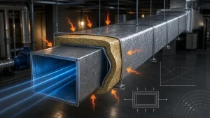
Maintain insulation continuity. Where duct is insulated, the insulation and vapor barrier must continue across fitting connections without gaps. Cold spots at fittings in humid environments can condense moisture, corrode metal, and create ceiling water damage.
Plan access before closing. Identify every damper, sensor, filter, and cleanout in the system and confirm that an access door or removable panel is in place before walls and ceilings are closed.
Test and balance. Leakage testing confirms that the sealed system meets the specified leakage class. Testing, adjusting, and balancing (TAB) then measures actual airflow at each terminal and adjusts dampers to bring the system to design values. Systems with well-chosen, properly installed fittings generally require fewer TAB adjustments to reach design balance.
9. Common Duct Fitting Mistakes
| Mistake | Likely Result | Corrective Action |
|---|---|---|
| Short-radius or mitered elbow where space allows a long-radius fitting | Higher pressure loss, turbulence, noise at downstream diffusers | Replace with long-radius elbow; add turning vanes in rectangular mitered elbows where required |
| Tee used where a wye is physically feasible | Higher branch loss, uneven distribution, more balancing required | Replace with wye or angled lateral |
| Flexible duct compressed, kinked, or sharply bent | Increased resistance, reduced airflow, possible inner liner deformation | Extend fully, support to prevent sag, route with bends no tighter than one duct diameter radius |
| Eccentric reducer installed with wrong flat-side orientation | Condensate pools in duct; clearance lost | Remove and reinstall with flat side in correct orientation per drawing |
| Fitting forced into position to close a gap | Stressed joint, leakage under pressure cycling | Investigate root cause; replace with correctly sized or custom-fabricated fitting |
| Mastic applied to contaminated or wet surfaces | Adhesion failure, leakage at joint | Clean and dry all surfaces before applying sealant; inspect before enclosure |
| No independent support at heavy fittings | Joint loaded in bending or shear; eventual leakage or failure | Install hanger at or near each heavy fitting independently of the duct sections |
| No access door near dampers, filters, or sensors | System cannot be serviced without destructive ceiling or wall access | Install access fittings during construction; record locations on as-built drawings |
| Standard fittings ordered for non-standard equipment connections | Field-fabricated transition, leakage, and flow imbalance at equipment | Order custom fitting with equipment interface drawing before fabrication |
10. HVAC Duct Fitting Standards and Project Requirements
Duct fitting selection, fabrication, and installation are governed by the mechanical code and project specification applicable to each jurisdiction and building type. No single standard applies universally.
In the United States, the International Mechanical Code (IMC) sets minimum requirements for duct construction, materials, sealing, and installation. The SMACNA HVAC Duct Construction Standards provide detailed fabrication methods, gauge requirements, reinforcement schedules, joint types, sealing requirements, and pressure class classifications for rectangular, round, and flat-oval systems. These two references are the baseline for most US commercial projects.
In the United Kingdom, BESA DW/144 covers ductwork construction standards, and Approved Document F addresses ventilation performance requirements. Other regions have comparable national standards.
Specialized applications — commercial kitchen grease exhaust, smoke control, laboratory exhaust, cleanrooms, and industrial process ventilation — require additional project-specific standards beyond general HVAC ductwork requirements. Manufacturer installation instructions for proprietary fitting systems take precedence over general trade standards where the two conflict.
Always confirm the applicable code, specification, and authority requirements for each project before specifying materials, joint types, and sealing methods. [IL: HVAC duct systems]
11. Frequently Asked Questions About HVAC Duct Fittings
Q1: What are the most common HVAC duct fittings?
The most frequently used fittings in commercial HVAC systems are elbows (direction changes), wyes and tees (branches), reducers and transitions (size and shape changes), couplings and flanges (straight connections), start collars and takeoffs (branch-to-trunk connections), register boots (terminal device connections), and end caps (sealing unused openings). The mix depends on duct shape, system layout, and equipment configuration.
Q2: Which duct fitting generally causes the most pressure loss?
Among common fittings, sharp branches and abrupt elbows typically contribute the most dynamic pressure loss per fitting. A tee — where branch air must make a sharp 90-degree turn — produces noticeably higher loss than a wye at the same airflow. Within elbows, a mitered rectangular elbow without turning vanes generally produces higher loss than a smooth long-radius elbow of the same angle, though the actual values depend on geometry, size, and flow velocity. The cumulative effect of all fittings in the longest duct run is what determines the system’s total external static pressure requirement.
Q3: When should HVAC duct fittings be custom fabricated?
Custom fabrication makes sense when the required angle, radius, size combination, or connection detail is outside catalog options; when the fitting must match a specific equipment flange that does not follow a standard pattern; when available installation space falls below catalog fitting dimensions; or when the material specification is not offered in standard production. Compare total installed cost — including field labor, delay risk, and leakage risk — not just component price. Provide a dimensioned drawing with your request and confirm site dimensions before placing the fabrication order.
Q4: What information should I provide when ordering duct fittings?
At minimum: fitting type and quantity, inlet and outlet dimensions, angle or branch configuration, material and gauge, connection type at each end, pressure class, and any insulation or lining requirements. For equipment connections, include the equipment model and interface drawing. For non-standard or complex pieces, include a dimensioned sketch or annotated drawing. Incomplete specifications are the most common cause of manufacturing errors and delivery delays.
12.Conclusion
Duct fittings are performance-critical components, not passive hardware. Each elbow, branch, reducer, and boot contributes to system static pressure, leakage, noise, and delivered airflow. Selecting the right fitting for each location — by function, geometry, duct shape, material, and connection type — is one of the most direct ways to improve system performance and reduce installation problems.
When the project layout moves outside standard catalog dimensions — because of equipment interface geometry, complex routing, or unusual material requirements — custom fabrication is often the lower-risk option once total installed cost is properly accounted for.
If you are sourcing fittings for a commercial, industrial, or specialized HVAC project, send your duct dimensions, pressure class, material requirements, and connection details.