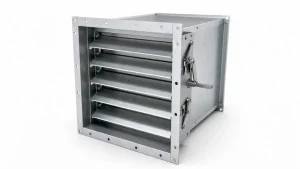
A volume control damper (VCD) regulates airflow through a duct section, branch, or zone by adjusting the position of one or more blades inside the ductwork. It is one of the most common airflow-control components in commercial and industrial HVAC systems—and one of the most frequently misspecified.
Getting the selection right starts before opening a product catalog. Blade type, material, actuator, sizing, and placement all depend on the specific airflow duty, duct geometry, system pressure, environment, and control requirements of the project. This guide covers each of those decisions in order.
1.What Is a Volume Control Damper?
A volume control damper is a duct-mounted device that controls the volume of air moving through a section of ductwork. One or more blades pivot inside the duct frame; as the blade angle changes, it alters the resistance the airflow encounters. More resistance means less air passes through that branch; less resistance allows more air through.
VCDs are installed at branch take-offs, zone connections, and other points in a duct system where airflow must be set, limited, or adjusted. They are used during testing, adjusting, and balancing (TAB) to proportion air between branches, and in automated systems they are operated by actuators that respond to BAS control signals.
The terms volume control damper, air volume damper, duct damper, and balancing damper are sometimes used interchangeably in HVAC practice, but their exact meaning can vary by manufacturer and project specification. Always confirm how a term is defined in the applicable project documents before specifying.
2.What Does a Volume Control Damper Do?
A VCD serves several related but distinct functions:
- Branch balancing: Setting airflow in a branch duct to its design value during TAB, then locking the blade in that position.
- Zone airflow adjustment: Reducing or increasing air delivered to a specific area as occupancy or load requirements change.
- Automated airflow modulation: Continuously varying blade position in response to a BAS signal when a motorized actuator is fitted.
What a VCD cannot do is equally important. A volume control damper redistributes available airflow—it does not create it. It cannot:
- Increase total system fan capacity
- Correct an undersized duct
- Compensate for a closed or failed fire or smoke damper
- Fix a blocked coil, dirty filter, or collapsed flex duct
- Override a failed actuator or incorrect control sequence
- Address significant duct leakage
When a zone has insufficient airflow, diagnose from the fan downstream—confirm total system airflow, check main and branch duct performance, then investigate the terminal. Closing and opening dampers without that upstream check only redistributes a shortage.
3.VCD vs. Balancing, Zone, Fire, and Smoke Dampers
| Damper Type | Primary Function | Manual / Actuated | Used for TAB? | Fire/Smoke Listed? |
|---|---|---|---|---|
| Volume Control Damper | Airflow regulation and balancing | Both | Yes | No |
| Balancing Damper | Fixed airflow distribution, set at TAB | Usually manual | Yes | No |
| Zone Damper | Zone-level airflow control via BAS | Usually actuated | Not primarily | No |
| Fire Damper | Fire containment at rated barriers | Fusible link or actuated | No | Yes |
| Smoke Damper | Smoke control per life-safety sequence | Actuated | No | Yes |
A standard VCD is not an acceptable substitute for a specified fire, smoke, or combination fire/smoke damper. These are separate products with separate listing requirements, installation specifications, access requirements, and maintenance obligations. If both airflow regulation and life-safety performance are needed at the same duct location, specify a listed combination assembly.
4.What Information Do You Need to Select a VCD?
Before comparing products, define these inputs for each damper location:
Airflow and duct geometry
- Required design airflow (CFM or m³/h)
- Duct shape (rectangular or round) and nominal dimensions
- Installation orientation: horizontal, vertical, or angled
- Available straight duct upstream and downstream
Operating duty
- Fixed balancing position set once at TAB and rarely changed?
- Remote adjustment needed after ceiling is closed?
- Continuous BAS modulation required?
System performance
- Expected airflow velocity at the damper face
- Available static pressure at the damper location
- Allowable pressure drop across the damper
- Required leakage performance
- Noise sensitivity in adjacent occupied spaces
Environmental conditions
- Standard dry indoor ductwork
- Coastal, humid, or corrosive atmosphere
- Food processing, pharmaceutical, laboratory, or washdown environment
Project requirements
- Applicable codes and standards
- Commissioning and TAB documentation requirements
- Life-safety separation requirements
5.How to Size a Volume Control Damper
Sizing a VCD means confirming the selected damper can pass the required airflow at an acceptable blade position, pressure drop, velocity, and noise level. Matching a damper to duct size alone is not sufficient.
Step 1: Confirm design airflow Start with the required airflow for the branch or zone from approved project documents (CFM or m³/h).
Step 2: Confirm duct dimensions The damper frame must match the duct cross-section at the installation point.
Step 3: Determine face velocity Face velocity is airflow divided by the damper’s net free area:
V = Q ÷ A
Where V is velocity (fpm or m/s), Q is volumetric airflow, and A is the net free area published by the manufacturer—not the gross duct area. Higher face velocity increases pressure drop, turbulence, and potential noise.
Step 4: Check pressure drop at design airflow Review the manufacturer’s pressure drop curve at the design airflow and expected blade position. A damper sized too small will require significant throttling to reach the airflow target, adding unnecessary resistance and potentially generating noise.
Step 5: Check leakage requirements If near-shutoff performance is needed, confirm the leakage class meets the project requirement. Leakage is classified per AMCA standards (Class I, II, or III) and reported as a maximum rate at a stated differential pressure.
Step 6: Verify actuator torque (motorized dampers) Confirm the actuator’s rated torque is sufficient for the damper’s blade area, expected pressure differential, and blade-seal friction. An undersized actuator will fail to fully open or close the damper.
Step 7: Review manufacturer performance data All steps above must be verified against the specific manufacturer’s published data—not generic industry estimates. Different blade profiles, frame constructions, and seal designs produce different performance curves at the same nominal duct size.
6.How to Choose the Right VCD Configuration
6.1 Parallel vs. Opposed Blades
Parallel-blade and opposed-blade VCDs can both be used for airflow regulation, but their airflow characteristics differ.
Parallel blades rotate in the same direction. As the blades move toward closure, airflow is deflected toward one side of the duct. This produces a directional discharge pattern at partial openings and a non-linear relationship between blade angle and airflow volume.
Opposed blades rotate in opposite directions. The symmetrical movement distributes airflow more evenly across the duct cross-section and produces a more predictable blade-position-to-airflow relationship at intermediate settings. Opposed blade action is often selected where consistent metering or modulation is required.
Neither configuration is universally superior. Final selection should follow the manufacturer’s published performance data and the project’s specific control requirements.
6.2 Manual, Cable-Operated, Remote, or Motorized
| Operator Type | Best Suited For |
|---|---|
| Manual quadrant / handle | Accessible locations; blade set at TAB and rarely changed |
| Cable-operated | Ceiling, shaft, or duct locations where direct access is impractical |
| Remote balancing (9V actuator + remote) | Where access panels or ceiling penetrations must be minimized |
| Motorized actuator (24V or 230V) | BAS-controlled zone, economizer, VAV, or demand-controlled ventilation |
Key question: If this damper needs readjusting five years from now, how will the technician reach it, and what tool will they use?
6.3 Galvanized Steel, Aluminum, or Stainless Steel
| Material | Typical Application |
|---|---|
| Galvanized steel | Standard dry indoor commercial ductwork |
| Aluminum | Coastal, higher-humidity environments; lightweight prefabricated assemblies |
| Stainless steel | Food processing, pharmaceutical, laboratory, washdown, or corrosive environments |
Match fastener, shaft, and bearing materials to the blade and frame. A galvanized frame with incompatible fasteners in a humid environment creates a corrosion risk at the contact points even if the blade material itself is appropriate.
6.4 Blade, Seal, and Frame Construction
Blade-edge seals and casing gaskets reduce air leakage past the blade at closed or low-flow positions. Leakage class should be specified based on the project’s actual performance requirements, not assumed as a default.
Frame rigidity matters for large dampers and high-pressure applications. A distorted frame binds blades, causes uneven leakage, and prevents full travel. Bearing quality affects long-term blade movement, particularly in systems with frequent modulation cycles.
7.Pressure Drop, Leakage, and Noise
These three performance factors should be evaluated together.
Pressure drop is the resistance the damper adds to the system at its operating blade position. A damper requiring significant throttling to reach its airflow target adds meaningful resistance the fan must overcome, increasing energy consumption across the system.
Leakage matters where the damper must close to near-shutoff: isolation of unused zones, energy management in variable-occupancy buildings, or pressure-control applications. AMCA Standard 500-D classifies damper leakage; the applicable class should be stated in the project specification.
Noise is a final-acceptance criterion, not just a selection note. A damper can achieve its airflow target while producing objectionable noise at the adjusted blade position—particularly at high duct velocity or with excessive throttling. Review the manufacturer’s noise data (NC or dB ratings) at the design airflow, not only at wide-open conditions.
8.Where Should a Volume Control Damper Be Installed?
Typical installation locations:
- Main supply duct splits, where airflow must be proportioned between major branches
- Individual branch take-offs serving zones, terminal units, or groups of outlets
- Return duct branches where return-air distribution is a project requirement
Accessibility is the most important placement criterion. Coordinate with:
- Ceiling type and access panel positions
- Insulation and vapor barrier details
- Structural members, sprinkler heads, lighting, and adjacent services
- Controls wiring and conduit for motorized dampers
- Required clearance for future actuator replacement or blade inspection
Do not finalize damper locations after ceilings are closed. An inaccessible balancing device typically means inadequate airflow adjustment for the life of the installation.
9.Volume Control Damper Installation Checklist
9.1 Inspect Before Installing
- Check for shipping damage: distorted frames, bent or binding blades, corroded fasteners
- Confirm tag, model, size, and airflow direction arrow against approved drawings
- Move the blade manually through its full range before installation; it should move freely with no binding
9.2 Install the Damper Square and Keep the Blades Free
- Install the frame square to the duct—a racked or twisted frame binds blades and causes uneven leakage
- Do not over-tighten flanges; deflecting the frame restricts blade travel
- Ensure duct sealant, insulation, and vapor barriers do not contact the blade, linkage, or operator mechanism
- Provide clear access for adjustment, inspection, and future actuator replacement
- After installation, confirm the blade moves freely through its full range with the operator connected
9.3 Verify Operators and Controls Before TAB
- Confirm manual handles, locking quadrants, and cable mechanisms operate correctly and hold position
- For motorized dampers: verify actuator mounting, wiring, control signal, and position feedback
- Command motorized dampers to full open and full closed from the BAS; confirm blade travel matches expected range
- Confirm all access panels are installed and openable without disturbing adjacent services
10.How VCDs Are Used in Air Balancing
Air balancing adjusts airflow throughout an installed system to meet design requirements. Two principles apply:
- The target is not equal airflow at every outlet—each branch and terminal has its own design value.
- Damper adjustments redistribute available airflow. Adequate total fan output must be confirmed before branch adjustments begin.
10.1 Verify System Airflow Before Adjusting Dampers
Confirm the system is complete and operational. Measure total fan airflow and compare with the design requirement. If total fan airflow is insufficient, branch damper adjustments redistribute a shortage—they do not correct it.
Do not use damper adjustments to conceal defects such as incorrect fan rotation, blocked coils, disconnected ductwork, or failed actuators. These must be corrected first.
10.2 Adjust Branch Dampers Proportionally
Identify over-supplied branches relative to their design airflow. Reduce flow in stronger branches incrementally, working toward the branch with the lowest measured-to-design ratio. Recheck upstream and downstream readings after significant adjustments—each change alters system resistance and affects connected branches.
10.3 Measure and Record Final Airflow
Core calculation:
% of Design = (Measured Airflow ÷ Design Airflow) × 100
Acceptance criteria are project-specific (SMACNA, ASHRAE 111, NEBB, or AABC as specified).
Minimum handover record per damper:
- Damper ID, tag, and installed location
- Design airflow and final measured airflow
- Final blade or operator setting
- Test mode and operating condition
- Measurement method and instrument
- Actuator model and control signal details (motorized)
- Unresolved deficiencies or inaccessible devices
11.Common VCD Problems
Always diagnose from the system level before adjusting individual dampers.
11.1 One Branch or Zone Has Low Airflow
- Confirm damper is in its recorded final position; check whether handle or actuator has shifted
- Inspect flex duct: compression, kinking, disconnection, or excessive length
- Check terminal unit maximum airflow setting, neck size, and any outlet restriction
- Verify upstream branch damper is not inadvertently partially closed
- Confirm total system fan airflow—far-end low airflow may reflect a capacity issue, not a single damper problem
11.2 Airflow Changes or Will Not Hold Its Setting
- Check actuator power, control-signal wiring, and position feedback
- Review control sequence: occupancy scheduling, static-pressure reset, VAV minimums, and economizer can produce intentional changes that appear as faults
- Check sensor calibration—a faulty temperature, pressure, or CO₂ sensor can drive unexpected damper movement
- Stabilize the required test condition before concluding the damper is defective
11.3 Noise or High Pressure After Balancing
- Identify the over-throttled damper; high velocity through a nearly closed blade is the most common cause
- Check whether total system static pressure has risen—closing multiple dampers raises system-wide resistance
- If a damper must remain nearly closed to achieve required airflow, investigate whether branch duct size, damper free area, system pressure, or upstream distribution is appropriate
- A completed balance satisfies airflow, pressure, and acoustic requirements together
12.VCD Maintenance
Scheduled inspection:
- Blade: distortion, corrosion, foreign material, physical damage
- Seals and gaskets: compressed, torn, or missing components affecting leakage
- Bearings and shafts: corrosion or binding preventing free blade movement
- Frame and flanges: corrosion, fastener failure, or movement affecting duct sealing
- Identification tags and setting marks: confirm readable and matching TAB record
Operator and actuator checks:
- Cycle manual dampers periodically; confirm locking mechanism holds
- Test motorized actuators from the BAS; confirm blade position matches command signal
After system changes: Any modification to duct routing, fan selection, terminals, zone configuration, control sequences, or building occupancy can invalidate original TAB settings. Rebalance affected portions of the system after significant changes.
13.FAQ
Q1:What Is the Difference Between a Volume Control Damper and a Balancing Damper?
In most field usage the terms are interchangeable. In a strict specification context, a balancing damper is typically set and locked during TAB to establish fixed airflow distribution. VCD may describe a broader category including motorized modulating devices. Always confirm how the term is used in the project specification.
Q2:Should VCD Blades Be Parallel or Opposed?
Both configurations are valid for airflow regulation. Parallel blades produce a more directional airflow pattern at partial openings. Opposed blades tend to provide more even distribution and a more predictable blade-position-to-airflow relationship, often preferred for modulating applications. Final selection should be based on manufacturer performance data and project control requirements.
Q3:How Do You Adjust a Volume Control Damper?
Measure actual airflow at the branch or outlet. Compare with the design target. Adjust the blade incrementally—open to increase flow, close to reduce it—and allow the system to stabilize between adjustments. Re-measure, then lock and mark the final setting. Record design airflow, final measured airflow, and blade position in the TAB documentation.
Q4:Can a VCD Be Used as a Fire or Smoke Damper?
No. Fire and smoke dampers must meet specific listing, installation, access, and maintenance requirements. A standard VCD is not listed for this purpose. Where both airflow regulation and life-safety performance are required at the same duct location, specify a listed combination fire/smoke damper assembly.
Q5:When Should HVAC Dampers Be Rebalanced?
After major equipment replacement, ductwork modification, control system changes, building renovation, significant occupancy change, or when measured airflow testing shows the system has deviated from design requirements.
14.VCD Selection: Where to Start
The selection sequence is consistent across every project:
- Define airflow duty, duct geometry, operating mode, leakage requirement, and environmental conditions
- Size the damper: confirm face velocity, pressure drop, and leakage at design airflow
- Choose blade action, material, and operator type to match the application
- Confirm placement supports accessible adjustment and future maintenance
- Install correctly, verify full blade travel, and confirm before TAB begins
- Balance to design airflow, document final settings, and hand over a complete TAB record
To prepare a technical submittal or request a quotation, have ready: design airflow, duct dimensions, installation orientation, blade action requirement, operator type, leakage class, environmental conditions, actuator control signal type, and relevant specification and drawing details.