Lead time and fabrication time are not the same thing. A duct package that requires three days of actual shop production can still carry a two-week lead time — because drawing approval, material availability, shop queue, quality checks, and delivery scheduling all sit outside the production window.
This distinction matters because it changes where you look for improvements. Buying a faster machine does not reduce a lead time driven by drawing revisions. Reorganizing the shop floor does not help when coil stock is on back-order. Effective lead time reduction starts with understanding which stage is actually adding the time — and targeting that stage specifically.
This guide covers typical duct fabrication lead times, the most common delay sources at each stage, the equipment and workflow changes that have the most practical impact, and a simple method for calculating and tracking your own lead time by stage.
It is written for HVAC contractors, duct fabrication shop owners, and production managers working to shorten the time from approved drawings to finished ductwork ready for installation.
1.How Long Does Duct Fabrication Take?
Duct fabrication lead time varies widely depending on project scope, shop loading, material availability, and whether drawings are approved before production begins. The ranges below reflect typical market conditions for shops running standard commercial HVAC duct in galvanized steel.
| Project Type | Typical Lead Time | Primary Variables |
|---|---|---|
| Simple / low-volume package | 3–7 business days | Standard materials, straightforward fittings, clear drawings |
| Medium-complexity project | 1–3 weeks | Mixed gauges, multiple fittings, moderate volume, some approval cycle |
| Large or complex project | 3–6 weeks | High volume, custom fittings, phased approvals, shop capacity constraints |
| Specialty materials | Add 1–4 weeks | Stainless steel, heavy gauge, special coatings or finishes |
These figures represent the full lead time from confirmed order to delivery — not fabrication time alone. A shop quoting “5-day fabrication” on a medium project may still carry a 2–3 week total lead time if drawing approval takes a week and material delivery adds another few days before production can start.
The key variables that move lead time in either direction:
- Drawing completeness and approval speed
- Material availability, particularly for non-standard gauges or coatings
- Current shop loading and queue depth
- Proportion of complex fittings versus straight duct runs
- Delivery distance and scheduling requirements
2.Duct Fabrication Lead Time vs. Production Time
Production time is the time the shop spends actively forming metal. Lead time is the total elapsed time from order or drawing approval to finished duct on-site. The two can be very different numbers, and confusing them leads to the wrong improvement decisions.
Consider a realistic example:
| Stage | Time |
|---|---|
| Drawing approval and RFI resolution | 3 days |
| Material procurement and delivery | 2 days |
| Shop queue before production starts | 2 days |
| Actual fabrication | 3 days |
| Quality inspection | 1 day |
| Delivery scheduling and transport | 1 day |
| Total lead time | 12 working days |
The shop’s fabrication time is 3 days. The project’s lead time is 12. Cutting fabrication time in half — from 3 days to 1.5 — saves 1.5 days on a 12-day lead time. Eliminating the drawing approval delay saves 3 days. Targeting the right stage has four times the impact of targeting the production floor.
This is why a faster machine does not automatically mean faster delivery. Production speed only improves lead time when production is the constraint — which, in most shops, it frequently is not.
3.What Causes Duct Fabrication Lead Time Delays?
Most lead time problems fall into one of five stages. The table below maps each stage to its common delay drivers and what to measure to identify whether it is your current constraint.
| Stage | Common Delay Drivers | What to Measure |
|---|---|---|
| Design and drawing approval | Late scope changes, unresolved multi-trade conflicts, RFIs | Days from order to approved drawings |
| Material procurement | Supply variability, no safety stock, incomplete orders at job start | Days from order to material on-site |
| Shop production | Bottleneck stations, inter-station handling, large batches, setup time | WIP accumulation, cycle time per set |
| Quality and inspection | End-of-run batch inspection, rework cascades from early errors | Rework rate, pieces rejected per run |
| Delivery and staging | No phased delivery plan, poor labeling, duct arriving out of sequence | Days between fabrication completion and installation start |
The most common mistake is applying a shop-floor improvement to a lead time problem that originates in drawing approval or material procurement. Measure each stage separately before deciding where to invest improvement effort.
4.How to Reduce Duct Fabrication Lead Time
4.1 Freeze Designs Before Production Starts
Late drawing changes are the single most disruptive lead time driver in duct fabrication — and the least frequently treated as a schedule variable. A revision after fabrication begins does not just cost rework time. It displaces a production slot, may scrap material, requires re-coordination with other trades, and can shift field crew scheduling.
Before releasing any job for fabrication, confirm:
- Final duct dimensions and routing for the full release scope
- Connection types at every joint — TDF flange, Pittsburgh lock, or angle-iron
- Special material specifications: gauge, coating, lining requirements
- Multi-trade coordination complete, particularly where ductwork intersects structural elements, piping, and conduit
BIM coordination and clash detection are the most cost-effective tools for achieving design freeze before production. A conflict identified digitally costs an hour to resolve. The same conflict identified when a formed duct section cannot clear a structural beam costs days of rework, rescheduling, and potential material loss.
4.2 Secure All Materials Before Releasing a Job
Starting production when 80% of the required material has arrived is not starting early — it is creating a partially completed job that will stop, occupy floor space, and require a full restart when the remaining material arrives. The restart time, re-sequencing, and disruption to other jobs typically costs more than the short delay of waiting for complete material availability.
For high-volume shops running standard commercial duct, carrying a safety stock of the most frequently used coil grades eliminates one of the most common production-stop causes. The cost of holding a buffer is almost always lower than the cost of a single production stop and delayed delivery.
For specialty materials — stainless steel, heavy gauge, coatings, or lined duct components — identify long-lead items at the quoting stage and place procurement orders before the fabrication window opens.
4.3 Identify the Production Bottleneck First
Applying a general efficiency improvement to the wrong station adds no lead time benefit. Before changing anything on the shop floor, identify where work is actually accumulating.
Walk the production flow from coil or blank to finished labeled duct. The station with the largest pile of work-in-progress waiting in front of it is constraining overall throughput. Improving a station upstream of the constraint only moves inventory forward faster — it does not increase finished output.
A common example: if the TDF flange forming station is running at capacity while the folding station is waiting, the constraint is flange forming. Adding operator time at cutting or blanking produces no additional completed duct. The fix belongs at the flange station — whether through an additional shift, adjusted break scheduling, or equipment upgrade.
4.4 Reduce Setup and Transfer Time
Non-productive time within and between stations accumulates quickly. Common sources in duct fabrication include:
- Setup and calibration at the start of each size change
- Time spent locating tools, fasteners, drawings, or work orders
- Moving partially formed duct sections between stations
- Sorting stacked blanks by type at downstream stations when the cutting table batched by cut profile rather than by duct set
Equipment layout changes — rearranging stations to shorten transfer distances — are often low-cost and produce immediate results. Tooling stored at the point of use, work orders available at each station rather than at a central office, and a simple visual location system for common tools reduce the time between forming cycles without any capital investment.
4.5 Use Automation for Repetitive Operations
Automated forming equipment delivers two lead time benefits: output speed and forming consistency. A auto duct production line that integrates blanking, notching, and TDF flange forming in a continuous CNC-controlled flow eliminates the manual layout and measurement steps that generate dimensional errors — and removes the rework cycles that those errors create downstream.
Consistency has as much impact as speed. Automated forming produces repeatable output across a full shift, which reduces the inspection overhead that accumulates when manual operations require periodic dimensional checks to catch drift. Fewer errors at forming mean fewer interruptions at inspection and fewer delayed deliveries caused by rework.
Semi-automatic configurations are worth considering where full integration is not yet justified. An integrated blanking line feeding a separate folding station, for example, can eliminate the highest-repetition errors at a fraction of the cost of a fully integrated system and may address the specific constraint without over-specifying other stages.
4.6 Control Batch Size and Order Release Timing
Fabricating significantly ahead of the field crew’s installation readiness creates inventory that must be stored, handled multiple times, and protected from damage. Each move adds handling risk, and if a drawing change occurs before installation, early-fabricated material may need to be modified or scrapped.
The practical rules for order release:
- Do not release a job until all required materials are confirmed available.
- Do not fabricate substantially ahead of the field crew’s confirmed readiness for that scope.
- Move complete duct sets through each station as a unit — do not batch by operation type across the full job.
- Do not allow the blanking or cutting station to run significantly ahead of the downstream capacity.
For shops using plasma or CNC cutting tables: nesting cuts to maximize material yield is correct. But once the nesting is complete, sort cut pieces by duct assembly set before moving downstream. Sorting at the cutting table takes minutes. Re-sorting at every subsequent station takes hours across a full run.
4.7 Align Production Sequencing With Field Installation
Delivering a complete duct order to a construction site weeks before installation creates site management problems that extend the project schedule from the field end. Storing heavy duct sections in a congested site, handling them repeatedly to clear access for other trades, and retrieving specific pieces from an unsorted stack all slow installation and increase damage and loss.
Phased delivery — producing and delivering duct in the sequence the field crew will install it, zone by zone or floor by floor — reduces on-site inventory, cuts handling time, and keeps the installation pace matched to shop output.
Piece-level labeling makes phased delivery workable. When every section carries a label identifying its building location, zone, and installation sequence, field crews install rather than sort. The coordination requirement is a regular conversation between the shop production schedule and the site installation plan — a step that rarely happens early enough on most projects.
4.8 Catch Errors Early With Inline Quality Checks
The cost of a dimensional error compounds with every downstream operation. An incorrect blank width caught before notching takes seconds to correct. The same error caught after the duct has been notched, formed, flanged, folded, and labeled requires undoing every subsequent operation — and delays delivery while consuming production capacity that other jobs were waiting for.
Inline quality checks at critical transitions are faster and cheaper than end-of-run batch inspection:
- After blanking: confirm cut length and width against the work order on the first piece before continuing
- After notching: verify notch geometry and corner squareness — inconsistent notches create poor corner fit-up at assembly
- After TDF flange forming: check flange profile on the first piece of each size program before committing to a full run
- After folding: measure fold angle squareness on the first piece of each new setup
Process verification before each run — confirming machine settings, tooling, and program parameters match the job — prevents rework more reliably than any post-production inspection protocol.
5.Which Duct Fabrication Machines Improve Production Time?
For shops where production is the lead time constraint, targeted equipment investment at the bottleneck station delivers the fastest return. The machines below address the most common production-stage delay sources in rectangular HVAC duct fabrication.
5.1 Auto Duct Production Line
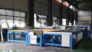
An auto duct production line integrates the most time-consuming and error-prone operations in rectangular duct production into a single continuous flow: coil decoiling, leveling, beading, notching, cutting to length, Pittsburgh lock seam forming, TDF flange forming, and folding. Material moves from raw coil to a formed duct panel without manual transfer between stations.
The lead time impact is twofold. First, automated forming eliminates the manual measurement and layout steps that generate dimensional errors and downstream rework. Second, the integrated station sequence removes the inter-station handling and queuing time that accumulates between separate machines. For shops where production throughput is the constraint, an auto duct line addresses both the speed and the consistency issues simultaneously.
Different configurations — Line 2 through Line 5, linear or U-shape layouts — suit different production volumes, floor space conditions, and output requirements. Selecting the right configuration starts with understanding what stage is currently limiting throughput and what the shop’s realistic daily demand requires.
5.2 CNC Plasma Cutting Machine
Straight duct production on a coil line does not address fittings, transitions, and custom blanks. For shops where fitting fabrication is a bottleneck, a CNC plasma cutting machine with nesting software handles complex cuts, non-rectangular profiles, and low-volume custom pieces with consistent accuracy and minimal setup.
Nesting software calculates the most efficient layout across the full sheet or coil before cutting begins, minimizing scrap material per job. For high-fitting projects — round-to-rectangular transitions, multi-branch takeoffs, offset sections — this equipment prevents the fitting production queue from becoming the downstream constraint that limits overall delivery speed.
5.3 TDF Flange Forming Machine
Where TDF flange forming is a standalone process rather than integrated into the main line, a dedicated TDF flange forming machine adds consistent flange geometry without the setup variation that accumulates across manual flanging operations. Consistent flange profiles reduce downstream rework at the corner insertion station and improve sealing performance in the field.
For shops currently running a manual or semi-manual flanging process, the most significant lead time benefit from this machine is the reduction in flange rework — a category that often creates invisible delays because the rework happens at the end of the production sequence, close to the delivery date.
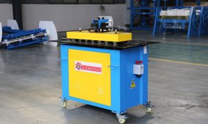
5.4 Lock Forming Machine
Pittsburgh lock seam forming on a [IL: lock forming machine] produces a consistent, airtight longitudinal seam across high-volume straight duct production. Machine-formed seams maintain uniform engagement along the full panel length, including at the ends near the flanges — a quality point that manual seaming struggles to maintain consistently at speed.
For shops still hand-forming lock seams on a proportion of their output, this represents both a throughput opportunity and a quality consistency improvement that reduces inspection and rework at final assembly.
6. How to Calculate Your Duct Fabrication Lead Time
Calculating lead time by stage — rather than as a single aggregate number — identifies where the time is going and where improvements will have the most effect.
Total Lead Time = Drawing Approval + Material Availability + Shop Queue + Fabrication Time + QC + Delivery
A worked example for a medium-complexity commercial duct package:
| Stage | Days |
|---|---|
| Drawing approval and RFI resolution | 3 |
| Material procurement and delivery | 2 |
| Shop queue before production slot opens | 2 |
| Actual fabrication | 3 |
| Quality inspection | 1 |
| Delivery scheduling and transport | 1 |
| Total lead time | 12 working days |
With this breakdown, it is clear that fabrication itself accounts for only 3 of the 12 days. Cutting fabrication time by 30% saves less than one day on the total. Eliminating the drawing approval delay saves three days. Removing the shop queue through better scheduling saves two.
Track this breakdown across several recent jobs and the pattern of where your lead time actually accumulates becomes clear. That is the stage to target first.
7.When to Bring in a Specialist Fabricator
In-house lead time improvements have limits. When the shop’s practical capacity is the constraint — not workflow, not organization, not equipment speed — the only paths are capital investment or outsourcing to a specialist fabricator with available capacity.
The scenarios where outsourcing shortens total project lead time rather than adding a coordination layer:
- Project volume exceeds realistic shop throughput for the delivery window
- The project requires consistent duct geometry across multiple sites where regional shops introduce quality variation
- BIM data exchange capability is required for direct CNC programming without manual re-entry
- The schedule requires a delivery commitment that the in-house shop cannot guarantee
When evaluating a specialist fabricator, the relevant criteria are:
- Confirmed lead time for your specific volume and duct configuration — not theoretical throughput under ideal conditions
- Phased delivery capability: can they sequence deliveries to match your installation plan?
- Quality consistency: SMACNA pressure class compliance, material certification, inspection records
- BIM file compatibility and the formats they require for CNC programming
Using a single fabricator for the complete scope — straight runs and fittings together — eliminates the inter-supplier coordination overhead and the separate delivery schedules that each add unpredictability. Two suppliers delivering to the same project on independent schedules doubles the coordination load and creates a schedule dependency at the seam between their scopes.
8.FAQ
Q1: How long does duct fabrication typically take?
Answer: Simple duct packages typically take 3–7 business days. Medium-complexity projects run 1–3 weeks. Large or complex projects can run 3–6 weeks. These figures cover the full lead time from approved drawings to delivery — not fabrication time alone. Drawing approval, material procurement, shop queue, and delivery logistics all add time outside the production window.
Q2: What causes duct fabrication lead time delays?
Answer: The most common causes are late drawing changes after production has started, material arriving incomplete before a job is released, bottleneck stations accumulating work-in-progress, end-of-run inspection finding errors that require rework, and delivery not sequenced to match field installation readiness. Each stage contributes independently, and the dominant cause varies by shop.
Q3: What is the difference between duct fabrication lead time and production time?
Answer: Production time is the hours the shop spends actively forming metal. Lead time is the total elapsed time from order or drawing approval to finished duct on-site — which includes drawing approval, material procurement, shop queue, fabrication, inspection, and delivery. A job with 3 days of fabrication time can still carry a 12-day lead time if other stages add delays.
Q4: Does an automatic duct production line reduce fabrication lead time?
Answer: Yes, when production is the constraint. An auto duct production line reduces fabrication time by integrating blanking, notching, TDF flange forming, and folding into a continuous flow, eliminating inter-station handling and reducing dimensional errors that cause rework. If the lead time is dominated by drawing approval or material delays, production equipment investment will have limited impact on the total lead time until those stages are addressed.
Q5: What factors affect ductwork fabrication lead time the most?
Answer: Drawing approval speed, material availability, current shop loading, the proportion of complex fittings in the job, and delivery sequencing. For most shops, drawing approval and material procurement account for more total lead time than the fabrication stage itself — which is why production improvements alone often deliver less lead time reduction than expected.
Q6: How can I increase duct production capacity without adding a full production line?
Answer: Start by identifying the bottleneck station — where work-in-progress accumulates — and target improvements there first. Options include staggering operator breaks to keep the constraint station running continuously, adding a standalone TDF flange forming machine or lock forming machine at the specific constraint, reducing setup time through better tooling organization, and implementing inline quality checks to catch errors before rework accumulates at the end of the run.