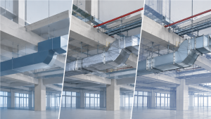

Contractors comparing LOD 300 vs LOD 350 vs LOD 400 are usually trying to answer a practical question: what can the team reliably do with the model it receives? LOD 300 generally supports developed design representation; LOD 350 adds information needed to coordinate interfaces; and LOD 400 develops agreed elements for fabrication, assembly, or installation.
A higher LOD is not automatically better. The right requirement depends on the model’s intended use, the project scope, and what the contract and BIM Execution Plan (BEP) specify. Clear definitions help prevent a coordination model from being mistaken for a production model—and keep teams from paying for detail they will not use.
1. What LOD 300, LOD 350, and LOD 400 Tell a Contractor
LOD stands for Level of Development. It communicates how developed and reliable the information associated with a model element is for a defined project use. It is not simply a visual-detail score: a highly rendered object can still lack the information needed for coordination or fabrication.
Level of Development is distinct from Level of Detail, which usually refers to graphical detail. A model can look simple yet provide reliable information for a particular decision; conversely, a visually elaborate model may not be suitable for shop production.
The BIMForum LOD Specification provides a shared vocabulary for describing model development. It does not, by itself, determine which level every element must reach or when. Project requirements, exchanges, responsibilities, and acceptance criteria should be defined in the BEP, contract, or other agreed project documents.
2. How the Model Changes from Design to Coordination to Fabrication
A pipe run helps illustrate the progression. At LOD 300, the model represents design intent with defined geometry and location. At LOD 350, it adds interfaces relevant to coordination, such as supports, insulation envelopes, sleeves, or clearances where required by the scope. At LOD 400, it is developed with the system-specific information agreed for fabrication or installation.
The table below is a practical MEP-oriented summary—not a universal checklist or a substitute for project-specific requirements. Exact content varies by element, trade, and intended use.
| Comparison | LOD 300 | LOD 350 | LOD 400 |
|---|---|---|---|
| Geometry | Defined size, shape, and location for the design use | Defined geometry plus coordination interfaces | Geometry developed for the agreed fabrication or installation use |
| Duct routing | Design-intent routing | Routing coordinated with adjacent systems and relevant clearances | Routing developed to the agreed production scope |
| Supports | Included as required by the design scope; not necessarily production-detailed | Coordination-relevant supports and interfaces where required | Detailed support components where the fabrication scope requires them |
| Connections | Design-level information as specified | Interfaces with adjacent elements | Specific joints and connection details where required |
| Fabrication details | Generally not included unless separately specified | Not necessarily included | Included as required for fabrication |
| Main application | Design documentation and review | BIM coordination and clash review | Fabrication, assembly, and installation workflows |
2.1 LOD 300: Is the design represented clearly enough?
LOD 300 represents elements with defined size, shape, location, orientation, and other information needed for the stated design purpose. It helps the team understand what is being designed and supports design development and documentation workflows where the model information has been specified as reliable.
For a contractor, LOD 300 can be a useful starting point for reviewing the design and planning work. Do not assume it includes trade-specific interfaces, final manufacturer selections, fabrication dimensions, or all information required to produce shop drawings. Include those items explicitly if the receiving team depends on them.
2.2 LOD 350: Do the systems fit and coordinate?
LOD 350 adds relationships between elements and adjacent systems that matter for coordination. Depending on the scope, that may mean representing supports, connections, sleeves or openings, insulation envelopes, and access or maintenance clearances. The goal is to show interfaces that affect whether systems can share the available space—not to model every small component.
This level can support BIM coordination and clash review. For example, a pipe route may appear clear at design level, but its insulation envelope, support arrangement, or required clearance can affect neighboring services. LOD 350 helps teams identify those issues before they become field questions, provided the relevant elements and criteria are part of the coordination scope.
A coordinated model is not necessarily a fabrication model. It may show that a system fits without containing the final connection types, production segmentation, or shop-specific information needed to build it.
2.3 How LOD 350 and LOD 400 Differ in HVAC Ductwork
HVAC ductwork provides a practical example of the difference between LOD 350 and LOD 400. At LOD 350, a duct model may represent duct dimensions and routing, the insulation envelope where required, coordination-relevant supports or interfaces, and clearances needed to review its relationship with other building systems.
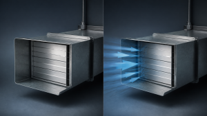
At LOD 400, the duct elements are developed with the fabrication information required by the agreed production scope. Depending on the project, that may include fitting configurations, connection details, flange arrangements, duct sections, and fabrication dimensions.
A coordinated rectangular duct model can show that the route fits within the available ceiling space. A fabrication-level model may also need to define how each section is constructed, connected, and prepared for production. The required details vary by project and manufacturer; not every ductwork scope needs the same flange, connection, or processing information.
For fabricators, a clearly defined handoff from HVAC ductwork fabrication design to production helps distinguish coordination information from shop requirements. The model should not be treated as a fabrication instruction unless the agreed scope and checks support that use.
2.4 LOD 400: Can the shop fabricate and install from the model?
LOD 400 develops the agreed elements with information required for fabrication, assembly, or installation. In MEP work, this may include specific fittings and joints, support details, fabrication dimensions, assembly information, or spool breakdowns. The content depends on the trade, production method, and deliverable requirements.
A useful test is to ask whether the shop can use the model for the intended production task without having to infer or recreate critical information. If key product data, connection choices, or installation decisions remain unresolved, the model may not be ready for that task—even if it is labeled LOD 400.
Fabrication-level development should start with the inputs that affect the build: current coordinated backgrounds, approved product or manufacturer information where required, agreed fabrication methods, and defined outputs. State whether the deliverable includes shop drawings, schedules, tags, spool or assembly information, or production data.
3. LOD 300 vs. 350 vs. 400: Which Level Fits Your Project?
Select the level by starting with the decision the model must support—not by choosing the highest number available. Ask who will use the model, what they need to verify or produce, and what information must be dependable at that point in the project.
| Choose | When the primary requirement is | Check before specifying |
|---|---|---|
| LOD 300 | Developed design representation, review, or documentation | Are coordination interfaces or fabrication outputs outside this handoff? |
| LOD 350 | Resolving spatial relationships and interfaces among trades | Which clearances, supports, penetrations, and connections are in scope? |
| LOD 400 | Fabrication, prefabrication, assembly, or installation information | Are product data, fabrication decisions, and production deliverables defined and available? |
LOD 400 is more likely to be useful when a project relies on prefabricated assemblies, has congested service zones, or needs model-based information for shop production. It may be unnecessary for simple runs or areas where the agreed task is limited to design review or coordination. The value depends on the project workflow and the cost of producing and checking the additional detail.
A single project can use different levels for different elements or milestones. For example, a trade may need fabrication-level development in a congested plant area while other elements remain at coordination level. Specify each requirement according to its use rather than forcing the entire project into one uniform LOD.
3.1 Does Shop Drawing Production Require LOD 400?
No. Shop drawing production does not automatically require every model element to reach LOD 400. Depending on the project requirements, LOD 300 or LOD 350 models may provide sufficient information for coordinated shop drawings, with additional dimensions or detailing supplied on the drawing sheets.
LOD 400 is more appropriate when the model itself must contain the fabrication, assembly, or installation information needed for production. A coordinated duct or pipe model may support installation planning without containing every fabrication joint, connection detail, or spool breakdown.
Before specifying LOD 400, define whether the deliverable requires coordinated shop drawings, a fabrication-level model, or both. This makes the expected work clearer and can prevent unnecessary modeling costs.
3.2 Define the LOD Scope Before You Bid or Accept a Model
A bare requirement such as “LOD 300/400” leaves too much open to interpretation. It can blur the boundary between design-team work, coordination work, and trade detailing—leaving teams to discover after award who is expected to develop the model and who pays for that effort.
Before pricing or accepting a BIM deliverable, clarify the following in the BEP, subcontract, or model-delivery requirements:
- Elements and intended use: Identify which systems or components are included, what decisions the model must support, and at which project milestones.
- Level-specific content: Describe required geometry and information rather than relying on the LOD label alone. State the coordination interfaces or fabrication details that matter to the scope.
- Ownership and inputs: Name who develops each stage and who supplies or approves product data, installation methods, and other information needed to progress the model.
- Outputs and exclusions: Specify whether the deliverable includes a model only or also drawings, schedules, tags, spool or assembly information, and production files. List exclusions that could otherwise be assumed.
- Review and exchange process: Agree on model exchange requirements, update timing, review and approval steps, and responsibility for responding to coordination comments.
- Commercial boundary: Include additional detailing effort in the bid or define how changes in scope will be handled. Do not assume a downstream fabrication model is included in a design-model fee.
Clear wording protects both the party issuing the model and the team relying on it. It also gives estimators a better basis for pricing the work rather than carrying an undefined modeling risk.
4. Handoff Checklist: Is the Model Ready for Its Next Use?
A model should pass a use-based review before it moves to the next team. The LOD label is a starting point; acceptance depends on the agreed scope, current information, and the receiving workflow.
- Confirm the requirement: Check the stated LOD by element, intended use, milestone, and acceptance criteria against the BEP or contract.
- Verify the model version: Confirm that the current design and coordination backgrounds are being used and that relevant revisions have been incorporated.
- Review coordination needs: Check the interfaces, clearances, penetrations, and other relationships required by the project—not only the visible geometry.
- Check fabrication inputs: Before production release, confirm the specified components, connections, dimensions, approved product information, and fabrication assumptions that affect the output.
- Validate the handoff: Check model placement, naming, version, and exchange requirements. Where practical, inspect the exported deliverable in the receiving team’s workflow.
- Record open items: Document unresolved clashes, assumptions, exclusions, comments, and approvals before release.
This checklist supports a controlled handoff; it does not replace project-specific engineering review, trade coordination, or required approvals. If the model is intended to drive production, the fabricator should confirm that the required information is present and usable before material is committed.
5. Common LOD Mistakes That Create Rework
Several avoidable assumptions can turn a model handoff into a scope dispute or field problem:
- Equating appearance with reliability. A detailed-looking object may not contain accurate or complete information for the intended use.
- Treating LOD 350 as fabrication-ready. Coordination can show that systems fit while leaving production decisions and shop details unresolved.
- Requesting LOD 400 everywhere. Additional development has a cost; concentrate it where the project will use the fabrication information.
- Using “LOD 300/400” as a complete scope. The phrase does not identify elements, deliverables, responsibilities, or who pays for the transition.
- Starting fabrication detailing with unresolved inputs. Product selections, submittals, connection methods, or design decisions may change the model and force avoidable rework.
- Confusing LOD 400 with LOD 500. In the BIMForum LOD Specification, LOD 500 represents existing conditions based on field verification or other stated verification methods. It is not a higher level of geometric development than LOD 400; the required accuracy should be defined separately.
- Assuming clash detection guarantees coordination. Software can help identify potential conflicts, but teams still need agreed review responsibilities and a process for resolving them.
6. Frequently Asked Questions
Q1: What is the main difference between LOD 300 and LOD 350?
Answer: LOD 300 represents defined design geometry and information for its intended use. LOD 350 adds the interfaces and relationships needed to coordinate the element with other systems.
Q2: Is LOD 350 suitable for clash detection?
Answer: It can support clash review because it includes coordination-relevant interfaces. The model still needs the elements, clearances, and coordination criteria required by the project.
Q3: Does shop drawing production require LOD 400?
Answer: No. Some projects can produce coordinated shop drawings from LOD 300 or LOD 350 models, with additional detail provided on the drawings. LOD 400 is appropriate when the model itself must support the agreed fabrication or installation workflow.
Q4: Does LOD 400 mean a model is automatically ready for fabrication?
Answer: No. It must contain the fabrication information required for the specific trade and production task, based on current and sufficiently resolved project inputs.
Q5: Does every MEP contractor need LOD 400?
Answer: No. LOD 400 is useful when fabrication, prefabrication, assembly, or installation depends on model-based production information. A coordination-only scope may need LOD 350 instead.
Q6: Can different elements in one project have different LODs?
Answer: Yes. Requirements can vary by element, system, project stage, and intended use. The scope should make those differences explicit.
Q7: Who should pay to develop a design model into a fabrication model?
Answer: The contract or project delivery requirements should assign that responsibility. Contractors should clarify the modeling scope and price the detailing work before committing to a downstream fabrication deliverable.
Q8: Is LOD 400 the same as LOD 500?
Answer: No. LOD 400 provides the detail required for fabrication, assembly, or installation. LOD 500 represents existing elements based on field verification or other specified verification methods. Its accuracy requirements should be established separately; it is not simply a more detailed version of LOD 400.
The practical distinction is straightforward: LOD 300 communicates the developed design, LOD 350 supports coordination, and LOD 400 supports the agreed fabrication or installation task. Shop drawings do not automatically require a full LOD 400 model. Before bidding, modeling, or releasing work to a shop, define the required information by element and use, then verify the handoff against that scope.