1. Introduction
Air does not always move through a duct in the same way. Depending on velocity, duct size, geometry, and internal surface quality, airflow can be smooth and orderly (laminar) or irregular and mixing (turbulent). For HVAC engineers, contractors, and duct manufacturers, understanding this difference is not just theory—it directly affects pressure loss, fan energy, duct noise, air distribution, and how easy a system is to balance.
For a duct fabrication business, there is one more practical point worth stating early: high-quality duct manufacturing cannot control every flow condition, but it can significantly reduce the unnecessary turbulence caused by dimensional errors, rough internal surfaces, misaligned joints, deformation, and leakage.
2. What Is Laminar Flow in HVAC Ducts?
In laminar flow, air moves in relatively parallel, stable, and orderly layers with little cross-mixing. Its typical characteristics include:
- Smooth, streamlined flow paths
- Relatively predictable velocity and pressure
- Weak lateral mixing between air layers
- Generally lower friction and local disturbance
In real HVAC systems, fully laminar flow across an entire duct network is uncommon. It is more likely in low-velocity, short, or small-section paths, and in specialized situations that require clean, directional supply air—such as certain laboratory or cleanroom zones. In most commercial and industrial ventilation systems, laminar flow throughout the whole duct run should not be assumed.
3. What Is Turbulent Flow in HVAC Ducts?
In turbulent flow, air velocity and direction fluctuate continuously, forming eddies, swirls, and irregular mixing. Its typical characteristics include:
- Stronger air mixing
- Generally higher pressure and friction losses
- A greater tendency toward noise, vibration, and uneven local velocity
- High sensitivity to elbows, branches, and internal components
Common causes of turbulence in HVAC ducts include:
- Higher air velocities
- Sharp elbows, tees, transitions, and eccentric connections
- Dampers, filters, diffusers, and control components
- Rough internal surfaces, raised seams, and installation misalignment
- Sudden changes in duct cross-section or internal obstructions
4. Laminar vs Turbulent Flow: Key Differences
| Dimension | Laminar Flow | Turbulent Flow | Meaning for HVAC Systems |
|---|---|---|---|
| Flow pattern | Smooth, parallel, orderly | Irregular, eddies, strong mixing | Affects supply stability and local resistance |
| Velocity behavior | Relatively stable | More fluctuating | Affects airflow distribution and comfort |
| Mixing ability | Weak | Strong | Affects temperature, humidity, contaminant dispersion |
| Pressure loss | Usually lower | Usually higher | Affects fan selection and energy use |
| Noise risk | Lower | Higher | Important for offices, hotels, hospitals |
| Predictability | Easier to model | More complex | Complex systems may need CFD or field testing |
5. How Reynolds Number Helps Identify Airflow Regime
The Reynolds number is a dimensionless parameter that compares inertial forces to viscous forces in a fluid, and it is commonly used to indicate whether flow tends to be laminar or turbulent:
Where:
- ρρ = air density
- VV = average air velocity
- DhDh = hydraulic diameter of the duct
- μμ = dynamic viscosity of air
As a general reference, a lower Reynolds number indicates a tendency toward laminar flow, a higher value indicates turbulent flow, and there is a transitional range in between. However, published threshold values vary between sources, so the Reynolds number should be treated as a starting indicator, not an absolute rule for every duct.
In real HVAC ductwork, the actual flow regime is also influenced by:
- Round, rectangular, or irregular duct cross-sections
- Duct size and aspect ratio
- Internal surface roughness
- Flanges, seams, and reinforcements
- Elbows, tees, transitions, and valves
- Upstream equipment and fan-outlet disturbance
In other words, the number is where the analysis begins—it does not replace proper duct design, system testing, and commissioning.
6. Where Turbulence Starts in HVAC Duct Systems
- Fan Discharge and Equipment Connections Fan outlets often produce uneven velocity profiles and swirl. Placing a sharp elbow, abrupt transition, or immediate branch right after the fan tends to increase local turbulence and pressure loss. Providing a reasonable straight run and smooth transitions helps the flow develop.
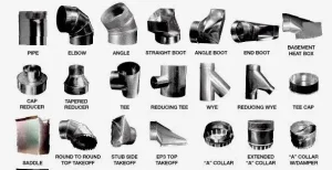
- Elbows, Tees, and Branch Takeoffs Sharp elbows create velocity differences between the inner and outer walls, along with flow separation and local recirculation. Tees and branches redistribute airflow and affect the balance of each run. Proper elbow radius, turning vanes, and branch design help reduce wasted resistance.
- Transitions and Sudden Size Changes Sudden expansion or contraction of the cross-section causes abrupt velocity changes and local energy loss. Smooth transitions help maintain more stable, developing flow.
- Dampers, Filters, and Air Terminals Damper position, filter resistance, and diffuser design all reshape the airflow. These components are key locations for system balancing and noise control.
7. How Turbulence Affects HVAC Performance
- Pressure Drop and Fan Energy Unnecessary turbulence raises local resistance and total static pressure demand, which can increase fan energy consumption.
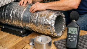
- Noise and Vibration Air impact, eddy shedding, and high local velocities can raise duct noise, while uneven seams, loose parts, and installation errors can amplify vibration.
- Air Distribution and Thermal Comfort Complex turbulence can cause airflow imbalance between branches, leading to uneven room temperatures and inconsistent comfort.
- Mixing, Ventilation, and Air Quality Moderate mixing helps even out temperature, humidity, and contaminant concentration. But uncontrolled turbulence can make supply paths unpredictable and increase the risk of short-circuiting or dead zones.
8. Does HVAC Design Need Laminar or Turbulent Flow?
This is the key point many articles miss. A well-designed HVAC system does not try to force fully laminar flow everywhere. Most real duct systems will contain some turbulence, and that is not automatically a problem.
The real design goal is to:
- Reduce unnecessary turbulence where stable, directional, low-disturbance supply is needed
- Use beneficial mixing where temperature uniformity matters
- Control local resistance, noise, vibration, and airflow imbalance
- Make airflow more predictable and efficient through good design and fabrication quality
| Application | Primary Airflow Priority |
|---|---|
| Offices & commercial spaces | Low noise, balanced airflow, comfort |
| Hospitals, labs, cleanrooms | Directional supply, low disturbance, contamination control |
| Industrial plants | Sufficient airflow, effective exhaust, durability, low loss |
| Kitchen / high-temp exhaust | Exhaust efficiency, local resistance, safety |
| Data centers / equipment rooms | Airflow organization, cooling, temperature uniformity |
9. How Duct Fabrication Quality Influences Airflow
This is where duct manufacturing capability directly supports airflow performance.
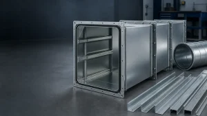
- Accurate Dimensions and Consistent Geometry Dimensional deviations, misaligned connections, and deformation can alter local velocity distribution. Stable forming, folding, and joining quality reduces irregular flow paths.
- Smooth Internal Surfaces and Clean Joints Internal burrs, raised seams, and loose joints act as extra turbulence sources. Precise cutting and clean assembly reduce unnecessary local resistance.
- Reliable Sealing and Leakage Control Leakage not only reduces delivered airflow but can also disturb branch pressure balance. Consistent flanges, seams, and sealing are a core foundation of system performance.
- Repeatability in Duct Production For project-based HVAC ductwork, repeatable accuracy makes installation and commissioning more controllable. This is where automated or CNC duct equipment adds value: dimensional consistency, production efficiency, connection quality, and standardized delivery.
10. Practical Tips for Controlling Unwanted Turbulence
- Avoid sharp elbows or abrupt transitions immediately after the fan outlet.
- Use elbows with a reasonable radius; add turning vanes where needed.
- Minimize unnecessary section changes and complex branch connections.
- Select duct size and velocity based on airflow and acceptable noise limits.
- Keep internal surfaces, seams, flanges, and connections as smooth and reliable as possible.
- Control leakage to prevent pressure loss and branch imbalance.
- Combine field airflow measurement, static pressure testing, and commissioning on complex systems.
- Use CFD to evaluate complex airflow zones on critical projects.
11. When Is CFD Analysis Useful for HVAC Ductwork?
CFD is most valuable for:
- Large commercial complexes, hospitals, labs, or data centers
- Complex networks with many branches, long runs, or multiple equipment connections
- Projects with strict noise, temperature uniformity, or clean-airflow requirements
- Fan rooms, special exhaust systems, or high-risk process ventilation
- Problem projects with recurring airflow imbalance, high local noise, or short-circuiting
CFD is well suited to identifying high-velocity zones, recirculation areas, concentrated pressure losses, and potential dead zones—but it should be used together with correct duct design, good fabrication quality, and proper field commissioning.
12 .Conclusion
The difference between laminar and turbulent flow directly influences pressure loss, noise, air distribution, and energy use in HVAC duct systems. In most real systems, turbulence cannot be fully eliminated—and is not always negative. What matters more is reducing unnecessary turbulence and local losses through sound duct layout, correct sizing, well-designed elbows and transitions, effective sealing, and high-quality fabrication. For complex HVAC projects, airflow design, precise manufacturing, and system commissioning should be treated as one integrated whole.
12. FAQ
In most real HVAC systems under typical operating conditions, airflow is turbulent or locally turbulent—especially near fan outlets, elbows, tees, transitions, and dampers.
Unnecessary turbulence and local resistance usually raise pressure loss and fan energy. The design goal is to control wasted disturbance, not to eliminate turbulence everywhere.
They change the velocity profile and can create flow separation, recirculation, and local pressure loss. Reasonable radius, smooth transitions, and turning vanes improve the flow.
Yes. Dimensional errors, misaligned joints, rough internal surfaces, raised seams, leakage, and loose connections all increase local resistance, noise, and airflow imbalance.
When the geometry is complex, airflow requirements are strict, or the project shows high noise, uneven airflow, hot spots, recirculation, or dead zones.