Air duct leakage does not appear randomly. It occurs at predictable locations — flanges assembled slightly out of alignment, gaskets installed with a gap at the corner, seams that were never fully closed during fabrication, or flexible connectors stretched under tension until the clamps no longer compress evenly.
Preventing air duct leakage means addressing those locations at the right stage: during fabrication, during installation, and again before the ductwork is concealed. This article covers where leaks typically occur, how to prevent them through correct fabrication and installation practice, which sealing methods to use and when, and how to verify results before handover.
1.Why Air Duct Leakage Matters
On the supply side, air that escapes through a seam or joint before reaching a diffuser is conditioned air that was never delivered. The HVAC system runs longer to compensate, increasing fan energy consumption and complicating system balancing.
Return-side leakage is a different problem. Return ducts running through ceiling plenums, plant rooms, or service corridors draw air from unintended spaces — potentially pulling in dust, exhaust gases, or contaminants and distributing them throughout the conditioned zone. This is why return duct connections require the same level of sealing attention as supply ducts.
Weak airflow at a diffuser or an unexplained rise in energy use are signals worth investigating, but neither is conclusive on its own. Blocked filters, incorrect fan operation, or closed dampers can produce the same symptoms. Confirm the actual cause before committing to duct repair work.
2.Where Do Air Ducts Usually Leak?
Knowing the most common leakage locations before installation or commissioning makes inspection faster and helps prevent defects from being concealed before they are corrected. These are among the most common locations where leakage occurs in HVAC duct systems.
2.1 Seams, Flanges, and Duct-to-Duct Joints
These are the highest-frequency leakage paths in any duct system because they are the most numerous. A large duct installation may contain hundreds of flange joints, and small individual gaps accumulate across a long run.
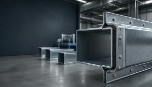
Longitudinal seams are formed during sheet metal fabrication. If the seam-forming equipment is not correctly adjusted, or the lock is not fully closed along the entire duct length, the seam becomes a continuous leakage path rather than a single-point defect. A poorly closed seam can release air along a meter or more of duct.
Flanged joints fail for several identifiable reasons:
- Gaskets installed with a break or overlap at the corners rather than running continuously around the full perimeter
- Flange faces bowed or distorted due to forming inconsistency
- Bolt spacing too wide, allowing flange faces to separate between fasteners
- Missing corner bolts — a common field assembly omission
- Misaligned duct sections placing uneven load across the gasket
Damage during transport and lifting — dented flanges, bent corners — often goes unrepaired because it is not immediately visible. These deformations prevent uniform gasket compression and should be corrected before assembly, not after the joint is tightened down.
2.2 Equipment and Accessory Connections
Connections between ductwork and installed HVAC components are among the most leakage-prone because they typically involve transitions between different geometries, are custom-fabricated per project, and are more likely to have dimensional variation.
Key locations to check:
- AHU and fan outlet transitions: The transition from a fan outlet or air handling unit to the first duct section is usually a project-specific fabricated piece. Poor dimensional fit or uneven flange compression creates leakage immediately downstream of the air source.
- Flexible vibration connectors: Installed between fans and ductwork to reduce vibration transmission. When a connector is installed under tension — because the gap is slightly larger than the connector length — the fabric or membrane is pulled taut and edge clamps may not compress evenly. Repeated thermal cycling accelerates cracking.
- Fire and smoke dampers: Flanges on both sides of the damper body are active leakage points. Misalignment, incorrect transition dimensions, or a displaced gasket at either face causes leakage. Sealing at fire and smoke control components must also comply with applicable project and fire safety requirements.
- Access doors and inspection openings: Access door gaskets are compressed and released repeatedly during maintenance — they deteriorate faster than gaskets at static duct joints. After any maintenance work, confirm all fasteners are fully re-engaged and the door closes flush.
- Return-air boxes and air terminals: Gaps between a ceiling return grille and its duct collar are easy to overlook because they are inside the ceiling void. Air drawn in from the ceiling plenum bypasses filtration and can introduce dust, fibres, or odors into the supply circuit.
2.3 Flexible and Specialty Duct Sections
Flexible duct and pre-insulated panel duct are sealed by different methods than sheet metal ductwork, and their failure modes reflect this.
Flexible duct connections depend on a clamp or draw band compressing the duct jacket over a collar. If the duct is not pushed fully onto the collar before clamping, the clamp grips the outer jacket without engaging the inner liner, and a leak path remains at the collar edge. Clamps work loose over time, especially where the duct sags or vibrates.
Pre-insulated duct systems — phenolic foam, polyurethane, or mineral wool panel types — use dedicated profile connections, adhesives, and tapes rather than metal flanges. Damaged panel edges, incomplete adhesive coverage, or a torn aluminum foil facing allow air to bypass the joint. The full perimeter of each joint needs checking, not just the center face.
One distinction that saves time during troubleshooting: a kinked or sagging flexible duct section restricts airflow but does not necessarily leak air out of the duct envelope. Treating an airflow restriction as a sealing failure leads to the wrong repair. Inspect for both physical damage and actual air escaping the envelope before deciding on corrective action.
3.Prevent Leaks During Design and Fabrication
The most cost-effective point to control air duct leakage is before sections leave the fabrication shop. Rework in the field — in a ceiling void, on a scaffold, or after insulation has been applied — is significantly more disruptive than correcting the same problem on a flat bench.
Define airtightness requirements before fabrication begins. The project specification should state the applicable leakage class, test pressure, and which parts of the duct system will be pressure-tested before handover. Without a defined target, fabricators and installers have no agreed standard, and commissioning teams have no basis for acceptance or rejection.
3.1 What Is Duct Leakage Class?
Duct leakage class describes the permitted airtightness performance of a duct system under a specified test pressure. Different project specifications, building standards, and industry guidelines use different leakage class designations and test pressures. The key point for fabricators and contractors is that the applicable class must be confirmed in the specification before production starts — it determines whether standard joint construction is sufficient or whether additional sealing measures are required.
3.2 Control Seam and Flange Quality During Fabrication
For sheet metal rectangular duct, the seam and flange are the two points where fabrication quality most directly determines installed system performance.
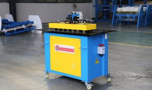
Seam forming: Set and verify seam-forming equipment at the start of each production run. Check the first section off the machine before continuing — an incorrectly adjusted seam former will repeat the same defect on every subsequent piece. The seam lock must close fully and consistently along the entire duct length.
Flange forming: Form flanges to consistent dimensions and check flatness across the flange face. A bowed flange cannot be corrected by over-tightening fasteners — it will compress the gasket unevenly and may deform the duct panel. Corner accuracy affects how well adjacent duct sections align and how uniformly the gasket compresses around the full perimeter.
Dimensional consistency: Duct sections from the same run need to fit each other. Variation in cross-section dimensions causes step misalignment at joints, which prevents full gasket contact regardless of how carefully the joint is assembled on site.
First-piece inspection and protection: Inspect the first completed section of any new profile or fitting before committing to a full production run. Install gaskets before sections are dispatched — unprotected flange faces and loose corners are common transport damage points that generate unnecessary field rework.
Match the sealing detail to the duct duty. Standard comfort-cooling supply ductwork, laboratory exhaust, smoke control ductwork, and clean room supply have different sealing requirements. Higher-pressure or more critical applications may require additional fasteners, different gasket materials, or sealant applied over the gasket. These requirements belong in the specification and should be confirmed with the [IL: HVAC duct fabrication] team before production begins.
4. Seal and Support Ducts Correctly During Installation
Consistent fabrication quality makes installation easier, but it does not eliminate the need for correct site practice. Most field-generated leaks come from a small number of repeatable errors.
Align flanges before sealing. Connecting two sections that are not properly aligned places uneven load on the gasket — one area compresses correctly, the adjacent area stays partially open. Bring flanges face-to-face before inserting fasteners, then tighten bolts in sequence, working progressively around the flange rather than fully tightening one corner before moving to the next.
Use compatible sealing materials. The standard options cover most applications:
| Sealing method | Typical application | Key requirement |
|---|---|---|
| Mastic sealant | Seams, irregular joints, fittings, supplementary sealing over gaskets | Allow full cure time before pressure testing |
| Foil tape (aluminum foil tape) | Clean, flat metal-to-metal seams | Surface must be clean and dry; not the sole seal at a flanged joint |
| Gasket | Flanged joints (primary seal) | Must run continuously around full perimeter including corners |
| Mastic + mesh reinforcement | Longer seams, larger irregular joints | More labor-intensive; provides additional structural support |
Standard household duct tape is not an acceptable substitute. It does not meet HVAC sealing performance requirements and degrades rapidly under thermal cycling.
Support ducts and connectors correctly. Flexible vibration connectors need enough slack to absorb equipment movement without transmitting vibration to the duct — but not so much excess length that they sag and buckle. Rigid duct sections need hangers at the intervals specified for the duct size and construction. Unsupported spans allow rotation and deflection that stress the joints at each end.
Inspect before insulating or closing the ceiling. Once the duct is covered, finding and correcting leaks requires opening finishes or removing insulation. Walk the entire accessible duct run before insulation is applied, checking every joint, access door, and equipment connection.
5. How to Check Ductwork for Leakage Before Handover
Visual inspection and pressure testing serve different purposes. Knowing which method applies — and what each can and cannot confirm — prevents time wasted on incomplete checks.
Visual and smoke-based detection is the appropriate first pass. Walk accessible duct runs and check:
- Flange joints for visible gaps, misalignment, or missing fasteners
- Seams along the duct body for incomplete closure or cracking
- Flexible connectors for tears, loose clamps, or visible tension
- Access doors for missing or degraded gaskets and unfastened closures
- Equipment transitions for dimensional mismatch or uneven clamping
Where line-of-sight is limited, a strong light source placed inside the duct while the exterior is inspected in reduced ambient light will reveal gaps. Smoke introduced to the duct interior can locate openings that visual inspection alone misses.
These methods are useful for finding obvious defects. They cannot quantify the total leakage rate of a system or confirm it meets a specified airtightness class.
Duct pressure testing provides a measured result. The system, or a defined test section, is pressurized to the specified test pressure, and the airflow required to maintain that pressure is measured — that measured airflow is the leakage rate.
To apply the result correctly:
- The test pressure must match the specification — results at different pressures are not directly comparable
- The test scope must be clearly defined; a passing result on one section cannot be applied to the whole system
- The acceptance criterion must be established in the specification before testing begins, not determined after seeing the numbers
- Defects found must be repaired and the section retested, not simply noted
Document tested sections, test conditions (pressure, ambient temperature), measured leakage, and the disposition of any defects. This record forms part of the project handover package.
Visual checks are not a substitute for pressure testing where testing is required. Whether testing is required is a project specification decision — confirm this before the duct system is installed and concealed.
6.What to Do If an Operating Duct System Is Already Leaking
For a system in service, confirm the problem is actually duct leakage before starting repair work. Weak airflow from one branch can result from a disconnected duct section, a blocked filter, a closed balancing damper, or an undersized run. Investigate the specific location and probable cause first.
Signs that suggest duct leakage rather than other causes:
- Significantly reduced airflow at specific outlets with normal performance elsewhere in the system
- Visible duct separation in accessible areas such as plant rooms or exposed ceiling voids
- Dust accumulation at or near duct seams in accessible spaces
- Musty or unusual odors that begin when a return duct section running through an unconditioned space is in operation
- Rattling or whistling at duct connections near the air handling unit that worsens when those connections are physically checked
Prioritize by impact. A fully disconnected duct section sending all its airflow into a ceiling void has a much greater effect than a partially open seam. Address detached sections first, then significant interface failures at equipment connections and access doors.
Repair options by defect type:
| Defect | Repair approach |
|---|---|
| Disconnected flexible duct | Reconnect fully onto collar, apply new clamp, confirm clamp engages inner liner |
| Failed flange gasket | Disassemble joint, clean flange faces, install new continuous gasket, reassemble with even fastener torque |
| Open seam on metal duct | Clean surface, apply mastic; for longer seams, use mastic with embedded mesh reinforcement |
| Damaged access door gasket | Replace gasket strip; verify door closes flush with all fasteners engaged |
| Corroded or structurally failed duct section | Section replacement — surface sealing is not appropriate for structural failure |
Correct the root cause, not just the visible symptom. A gasket that fails repeatedly may indicate distorted flange faces that create uneven compression — replacing the gasket without correcting the flange will produce the same result. A flexible connector that cracks at the clamp edge may be installed under tension; adding more clamps does not resolve the underlying problem.
After completing repairs, verify the result: check airflow at the affected outlets, inspect the repaired connections, and retest the section where project conditions allow.
7.Common Questions About Preventing Duct Leaks
Q1: What is the best way to prevent air duct leakage?
Answer: There is no single method. Effective prevention combines consistent dimensional accuracy during fabrication, correctly formed seams and flanges, appropriate gaskets and sealants applied to properly prepared surfaces, correct installation alignment and support, and leakage testing before the system is concealed. Addressing each stage is more reliable than relying on any single measure.
Q2: Does duct insulation prevent air leakage?
Answer: No. Insulation controls heat transfer between the duct and its surroundings — it addresses thermal performance and condensation risk, not airtightness. It does not seal the duct envelope against air escaping through seams and joints. Seal the duct correctly first; apply insulation over a properly sealed system.
Q3: Can duct cleaning fix a duct leak?
Answer: No. Duct cleaning removes accumulated dust and debris from inside the duct. Sealing a leak requires mechanical repair of the specific joint, seam, or connection where air is escaping. A cleaning inspection may identify a leak, but the cleaning process does not close it.
Q4: Do return ducts need to be sealed as carefully as supply ducts?
Answer: Yes — and in some respects return duct leakage has more complex consequences. Supply duct leakage loses conditioned air before delivery. Return duct leakage draws air in from unintended spaces, potentially pulling contaminants from ceiling voids, plant rooms, or adjacent zones into the system and distributing them throughout the building. Return ducts should be held to the same airtightness requirements as supply ducts.
Q5: At what stage should duct leakage testing be performed?
Answer: Before insulation is applied and before ceiling finishes are installed — while all joints and connections are still accessible and defects can be located and repaired without opening finishes. On projects where testing is specified, this timing should be programmed into the construction schedule at the outset, not treated as an afterthought during handover.
8.Conclusion
Most air duct leakage is preventable, and the most effective controls are applied early: accurate seam and flange forming in the fabrication shop, correct gasket installation and surface preparation during installation, and leakage testing before the system is concealed. Field repair is always more costly and disruptive than catching the same defect before it is sealed over.
For projects with defined airtightness requirements, treat testing and documentation as a standard handover deliverable, not an optional check. For existing systems already showing symptoms, locate the specific defect before applying a repair, and address the underlying cause — a distorted flange, an over-tensioned connector, or inadequate support — rather than covering the symptom.
The factors that determine duct airtightness are largely set during fabrication and installation. HVAC duct fabrication Getting those stages right is the most reliable way to reduce leakage, reduce rework, and deliver a system that performs as designed.