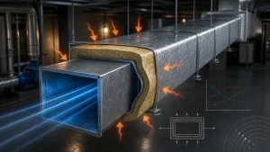
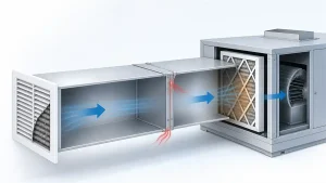
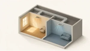
Conditioned air loses or gains heat as it travels through ductwork before reaching the occupied space. In heating mode, warm supply air loses heat to a cooler surrounding — duct heat loss. In cooling mode, cold supply air absorbs heat from a warmer surrounding — duct heat gain. The result in both cases is reduced delivered capacity, longer equipment runtime, and comfort problems that can be mistaken for undersized equipment.
This guide covers the two calculation methods engineers and contractors actually use, walks through a complete worked example with corrected energy-cost math, and provides practical guidance on insulation selection, condensation prevention, and field verification.
1. What Causes HVAC Duct Heat Gain and Heat Loss?
The driving force behind duct heat transfer is the temperature difference (ΔT) between the air inside the duct and the air surrounding it. The larger the ΔT, the higher the rate of heat transfer — and the more conditioned air energy is wasted before delivery.
Several variables determine how significant the loss or gain becomes in practice:
- Duct location: Ducts in unconditioned attics, crawlspaces, garages, rooftop plenums, or exterior chases face far larger ΔT values than ducts inside conditioned space. A supply duct carrying 55°F (13°C) air through a summer attic at 120°F+ (49°C+) faces a differential exceeding 65°F (36°C) — beyond what any practical insulation thickness can fully eliminate.
- Duct length and surface area: Longer runs and larger duct cross-sections expose more surface area. A 100-ft (30-m) main trunk in an unconditioned space accumulates substantially more heat transfer than a 15-ft (4.5-m) branch in a conditioned mechanical room.
- Insulation conductivity and thickness: Lower thermal conductivity (k-value) and greater thickness create higher thermal resistance. The relationship is not linear for round ducts — resistance grows logarithmically with added thickness.
- Air velocity: Higher velocity reduces residence time inside each duct section, so the temperature change per unit length is smaller. This effect is secondary and does not substitute for proper insulation.
- Duct leakage: Cracks, open seams, and unsealed joints allow conditioned air to escape before reaching the supply diffuser. This is a separate problem from conductive heat transfer — insulation does not stop leakage — and both must be addressed independently.
1.1 Conditioned Space vs Unconditioned Space
Routing ducts through conditioned or semi-conditioned space is the single most effective design decision for reducing distribution losses. When ΔT between duct air and surroundings is small — say, 5°F (3°C) in a well-controlled plenum — heat transfer through the duct wall is minimal regardless of insulation level.
Duct insulation requirements vary by jurisdiction, energy code version, duct location, system type, and project specifications. Before selecting an insulation R-value, verify the applicable requirements for the relevant jurisdiction and building type. Where condensation is a concern, insulation thickness and vapor-barrier design must also be assessed under expected operating and ambient conditions — not derived from a single code table.
2. How to Calculate Duct Heat Gain and Heat Loss
Two calculation methods are used in practice. They measure different things and suit different situations.
| Comparison Factor | Surface Heat Transfer Method | Airflow Temperature-Change Method |
|---|---|---|
| Primary inputs | Duct geometry, insulation properties, ambient temperature | Airflow (CFM or L/s), inlet and outlet air temperatures |
| Primary use | Design estimates, insulation option comparison | Field performance assessment |
| Key limitation | Depends on heat-transfer model and installation assumptions | Cannot isolate all loss sources independently |
2.1 Surface Heat Transfer Method
This method calculates heat exchanged between duct air and surroundings through the duct wall and insulation. The general steady-state form is:
Q = U · A · ΔT
Where:
- Q = heat transfer rate (W or BTU/hr)
- U = overall heat-transfer coefficient of the duct-insulation assembly (W/m²·K or BTU/hr·ft²·°F)
- A = duct external surface area (m² or ft²)
- ΔT = temperature difference between duct air and ambient (°C or °F)
The overall U-value is derived from the sum of thermal resistances in series. For a complete model these include:
- Inside air film resistance: Rsi = 1 / (hi · Ai)
- Duct wall conduction: typically negligible for thin sheet metal
- Insulation conduction: see below
- Outside air film resistance: Rso = 1 / (ho · Ao)
Inside film coefficients for typical HVAC duct airflows fall roughly in the range of 8–12 W/m²·K; outside coefficients range from approximately 5 W/m²·K (still air in a ceiling void) to 10 W/m²·K (typical indoor ambient) based on ASHRAE Fundamentals guidance. Actual values depend on air velocity, duct surface conditions, and configuration — these are reference ranges for preliminary design, not fixed constants.
For round insulated ducts, the insulation conduction resistance uses the cylindrical form:
R_ins = ln(r₂ / r₁) / (2π · k · L)
Where:
- r₁ = inner insulation radius (duct outer radius), m or ft
- r₂ = outer insulation radius = r₁ + insulation thickness, m or ft
- k = insulation thermal conductivity (W/m·K or BTU/hr·ft·°F)
- L = duct length (m or ft)
Total resistance: R_total = Rsi + R_ins + Rso
Heat transfer: Q = ΔT / R_total
For rectangular ducts, a planar average-area approximation is commonly used. This is acceptable at typical insulation thicknesses but becomes less accurate when insulation thickness approaches half the smaller duct dimension.
2.2 Airflow and Temperature-Change Method
When airflow and inlet/outlet air temperatures are available, heat transfer is calculated from the sensible energy change of the air:
Q = ṁ · Cp · ΔT
For practical HVAC work in imperial units, this simplifies to:
Q (BTU/hr) = 1.08 × CFM × ΔT (°F)
The constant 1.08 combines standard air density (0.075 lb/ft³), specific heat (0.24 BTU/lb·°F), and the minute-to-hour conversion (60 min/hr). For ΔT in °C, the constant becomes approximately 1.07. In SI units:
Q (W) = 1.2 × Qv (L/s) × ΔT (°C)
Important: The constants 1.08, 1.07, and 1.2 apply at standard conditions — approximately sea level and 20–21°C (68–70°F). At altitudes above approximately 600 m (2,000 ft) or at significantly different supply air temperatures, use the full formula with adjusted air density.
This method estimates the total sensible heat change of the airstream between two points. It cannot isolate conductive heat transfer from air leakage, mixing with adjacent air, or measurement error. Use it for overall performance assessment, not to validate insulation performance alone.
2.3 Worked Example — Calculating Duct Heat Gain and Annual Energy Cost
This example uses the surface heat transfer method for an insulated round supply duct in an unconditioned attic.
Given conditions:
- Duct air temperature: 55°F (cooling supply air)
- Ambient (attic) temperature: 95°F
- ΔT = 40°F
- Duct: round, 12 in inside diameter, 50 ft long
- Insulation: fiberglass blanket, 1 in thick, k = 0.023 BTU/hr·ft·°F
- Inside film: hi = 12 W/m²·K; outside film: ho = 5 W/m²·K (still air, ceiling void)
Step 1: Geometry
r₁ = 6 in / 12 = 0.500 ft
r₂ = 0.500 + (1/12) = 0.583 ft
Step 2: Insulation conduction resistance
R_ins = ln(0.583 / 0.500) / (2π × 0.023 × 50)
= ln(1.167) / 7.226
= 0.1542 / 7.226
= 0.02134 hr·°F/BTU
Step 3: Air film resistances
Converting film coefficients (1 W/m²·K = 0.1761 BTU/hr·ft²·°F):
- hi = 12 × 0.1761 = 2.113 BTU/hr·ft²·°F
- ho = 5 × 0.1761 = 0.881 BTU/hr·ft²·°F
Inside surface area: Ai = π × (12/12) × 50 = 157.1 ft² Outside surface area: Ao = π × (14/12) × 50 = 183.3 ft²
Rsi = 1 / (2.113 × 157.1) = 0.00301 hr·°F/BTU
Rso = 1 / (0.881 × 183.3) = 0.00619 hr·°F/BTU
Step 4: Total resistance and heat gain
R_total = 0.00301 + 0.02134 + 0.00619 = 0.03054 hr·°F/BTU
Q = 40 / 0.03054 ≈ 1,310 BTU/hr (insulated)
For comparison, removing insulation (film resistances only):
Q = 40 / (0.00301 + 0.00619) ≈ 4,350 BTU/hr (uninsulated)
Step 5: Annual energy cost
Three values must be kept separate: thermal heat transfer, cooling capacity required, and electrical energy consumed.
Insulated duct heat gain: 1,310 BTU/hr
Equivalent tons: 1,310 / 12,000 = 0.109 tons
Electrical demand (COP=3.0): 0.109 × 3.517 / 3.0 = 0.128 kW
Annual energy (2,500 hr/yr): 0.128 × 2,500 = 320 kWh/yr
Annual cost at $0.12/kWh: 320 × 0.12 ≈ $38/yr
Uninsulated: 4,350 BTU/hr → 0.427 kW → 1,068 kWh/yr → ~$128/yr
Adding 1-inch insulation to this 50-ft section reduces annual cooling cost by approximately $90/yr in this scenario.
Note: This example includes inside film, cylindrical insulation conduction, and outside film resistances. It excludes radiation to surrounding surfaces, thermal bridges at hanger supports, and duct air leakage. Treat results as first-pass design estimates, not final engineering calculations.
3. How to Estimate Annual Duct Energy Loss Across a System
Single-section calculations can be scaled to estimate system-level impact, but require several inputs: total duct surface area in unconditioned space, average seasonal operating ΔT, installed insulation R-value and condition, system COP at actual operating conditions, and annual operating hours at heating and cooling load.
The key distinction often missed: thermal load (BTU/hr of heat transferred through the duct wall) is not the same as electrical energy consumption (kWh). System COP must be applied before multiplying by operating hours and energy rate.
For commercial or industrial facilities with large duct networks and high operating hours, even modest heat-transfer rates per unit length accumulate into significant annual costs. Prioritize sections with the largest combination of surface area, high ΔT exposure, and long annual operating hours.
4. How to Choose Duct Insulation R-Value and Material
Insulation selection involves thermal performance, condensation risk, ambient exposure, and installation practicality. No single material or R-value is universally correct.
| Insulation Material | Typical k-Value (W/m·K) | Typical k-Value (BTU/hr·ft·°F) | Notes |
|---|---|---|---|
| Fiberglass blanket | 0.035–0.045 | 0.020–0.026 | Common for general HVAC; easy field install |
| Mineral wool | 0.030–0.040 | 0.017–0.023 | Good fire resistance and acoustic performance |
| Closed-cell foam | 0.020–0.030 | 0.012–0.017 | Inherently vapor-closed; suited for cold ducts |
| Polyisocyanurate (PIR) | 0.020–0.025 | 0.012–0.014 | High thermal performance per unit thickness |
| Elastomeric foam | 0.040–0.055 | 0.023–0.032 | Flexible; vapor-closed; used on cold duct surfaces |
k-values vary with product formulation, mean service temperature, and test conditions. Always use the specific product data sheet for design calculations. k-value ranks only thermal conductivity — it does not reflect moisture resistance, fire classification, UV durability, or mechanical protection.
For cold supply ducts, vapor barrier continuity is as critical as k-value. Any gap in the barrier allows moisture infiltration that saturates fibrous insulation and destroys its thermal performance. Closed-cell foam and elastomeric materials are inherently vapor-closed and are commonly specified on chilled-air duct sections.
For outdoor and rooftop ductwork, the outer jacket must be weather- and UV-resistant.
4.1 Diminishing Returns on Insulation Thickness
For round ducts, the cylindrical resistance term ln(r₂/r₁) grows progressively — each additional inch of insulation provides less incremental resistance than the previous inch. The actual energy savings difference between insulation levels depends on duct geometry, ambient ΔT, annual operating hours, and system efficiency. Calculate the specific project scenario rather than applying a generic rule.
5. Duct Condensation: Causes and Prevention
Condensation is primarily a cold-duct problem. When the outer insulation surface drops below the ambient dew point, moisture condenses. In humid environments, this affects chilled-water supply ducts, refrigeration air-handling ducts, and cold supply ductwork in unconditioned spaces during summer.
Sustained condensation causes water damage to ceilings and building materials, mold growth, progressive insulation saturation, and indoor air quality problems.
Design condition: The outer insulation surface temperature must remain above the expected ambient dew point under worst-case conditions. This requires knowing the design ambient dry-bulb temperature, relative humidity, and resulting dew point for the installation location.
The minimum insulation thickness for condensation control must be calculated for project-specific conditions — energy-code minimum R-values are derived for energy performance, not moisture management. In warm, humid climates, condensation-driven thickness requirements frequently exceed energy-code minimums.
Vapor barrier integrity is the second requirement. A correctly specified insulation thickness is ineffective if moisture can reach the cold surface through gaps or punctures. All overlaps, seams, fittings, and penetrations must be continuously sealed. Closed-cell foam and elastomeric insulation provide inherent vapor resistance; fibrous insulation depends entirely on the applied vapor barrier.
6. Duct Heat Gain vs Duct Leakage
These represent entirely different failure modes.
Conductive heat gain/loss passes through the duct wall and insulation due to temperature difference. Insulation reduces this by increasing thermal resistance.
Duct air leakage is conditioned air escaping through gaps, seams, and joints before reaching the supply diffuser. Insulation placed over a leaky duct does not reduce leakage — it conceals it.
Common leakage points include longitudinal seams on rectangular ducts, slip-fit and drive connections at fittings and takeoffs, flexible duct connections at collars and diffusers, and poorly sealed access panels.
Effective duct performance requires sealing before insulating.Duct leakage testing quantifies air loss directly and is the correct diagnostic tool for leakage-related distribution problems.
7. How to Measure Duct Heat Gain and Heat Loss in the Field
Measurement steps:
- Identify the duct section to evaluate and confirm inlet and outlet locations.
- Place temperature sensors at least 10 duct diameters downstream of any fitting, coil, damper, or junction to ensure representative temperature profiles.
- Use calibrated instruments. For ΔT below 2°C (3.6°F), ±0.1°C accuracy or better is required to distinguish real performance from measurement noise.
- Measure inlet temperature, outlet temperature, and ambient simultaneously — not sequentially.
- Allow at least 15–20 minutes of steady-state operation before recording. Average over a minimum 30-minute stable period.
- For cold ducts in humid spaces, also measure ambient relative humidity to assess condensation risk.
Interpreting field results: The outlet-minus-inlet ΔT reflects combined effects of conductive heat transfer, leakage, and measurement error. A larger-than-expected ΔT may indicate insufficient insulation, insulation damage, or significant leakage. Field measurements alone cannot always distinguish between these causes — investigate insulation condition and duct sealing before concluding that insulation specification is the problem.
In buildings with building automation systems, logging supply temperature trends over time often reveals gradual insulation degradation before it becomes a visible comfort complaint.
8. Duct Heat Loss Calculation Mistakes to Avoid
- Unit mixing: Applying SI k-values with imperial duct dimensions — or using BTU-based formulas with Celsius ΔT without conversion — produces large errors. Establish a consistent unit system before beginning.
- Confusing k-value, R-value, and U-value: k-value is a material property. R-value is resistance of a specific installed thickness (R = thickness ÷ k, with consistent units, for a homogeneous layer). U-value is the overall coefficient for a complete assembly.
- Applying cylindrical formulas to rectangular ducts: The round-duct cylindrical model does not apply to rectangular geometry. The planar approximation has accuracy limits at higher insulation thicknesses.
- Omitting air film resistances: Using only insulation conduction overstates thermal resistance, particularly for uninsulated or lightly insulated ducts where film resistance is a significant share of total resistance.
- Treating heat transfer and leakage as the same problem: The two require separate assessment.
- Using nominal insulation thickness as installed thickness: Compression at hangers, bends, and supports reduces effective thickness at those locations.
- Sizing cold-duct insulation only for energy performance: Condensation control may require greater thickness. Both criteria must be checked when both apply.
- Assuming formula constants apply at all conditions: The 1.08 (imperial) and 1.2 (SI) constants assume standard air density. At altitude or unusual supply temperatures, use the full density-corrected formula.
9. HVAC Duct Heat Gain and Heat Loss FAQs
Answer: Duct heat loss occurs in heating mode when warm supply air loses heat to a cooler surrounding, reducing delivered heating capacity. Duct heat gain occurs in cooling mode when cold supply air absorbs heat from a warmer surrounding, reducing delivered cooling capacity. Both waste energy before conditioned air reaches the space.
Answer: Use the surface heat-transfer method (Q = ΔT / R_total, with cylindrical resistance for round ducts) when you know duct geometry and insulation properties and need to evaluate or compare insulation options. Use the airflow temperature-change method (Q = 1.08 × CFM × ΔT) when you have measured supply temperatures at duct inlet and outlet. A complete analysis may use both.
Answer: No. Insulation reduces conductive heat transfer through the duct wall but does not seal gaps, seams, or fitting connections. Seal all joints with mastic or approved foil tape first. Insulating over leaky joints conceals the problem without solving it.
Answer: The temperature difference (ΔT) between duct air and surroundings is the primary driver. Attics in hot climates can reach 120°F+ (49°C+), creating a ΔT above 60°F (33°C) for cold supply air. Routing ducts through conditioned space reduces this differential more effectively than any insulation upgrade.
Answer: k-value (thermal conductivity) is a material property — lower means better resistance per unit thickness. R-value is the thermal resistance of a specific installed thickness: R = thickness ÷ k, with consistent units. Compare insulation materials by k-value; compare installed assemblies or check code compliance by R-value.
Answer: Condensation is a cold-duct problem in cooling mode. When the outer insulation surface temperature falls below the ambient dew point, moisture condenses. Preventing this requires sufficient insulation thickness and a continuous vapor barrier — energy-code minimum R-values do not always satisfy condensation-control requirements, particularly in warm, humid climates.
Answer: Keep three values distinct: (1) thermal heat transfer through the duct wall in BTU/hr or watts; (2) equivalent cooling or heating capacity; (3) electrical energy consumed after dividing by system COP. Treating thermal load directly as electrical consumption without applying COP overstates the energy cost estimate.
Answer: For code compliance documentation, chilled-water or refrigeration systems with condensation risk, high-humidity industrial or process ventilation, large commercial load calculations, and forensic assessment of comfort complaints or moisture damage. Online calculators are useful for screening — they are not substitutes for project-specific engineering where error consequences are significant.
10. Conclusion
Duct heat gain and heat loss reduce delivered HVAC capacity, increase energy consumption, and generate comfort problems that persist through multiple equipment replacements if the distribution system is never properly evaluated. The two calculation methods covered here address different questions: surface heat-transfer formulas for design and insulation comparison; airflow temperature-change measurements for field verification.
The practical priorities are consistent across project types: route ducts inside conditioned space where possible, seal all joints before insulating, select insulation based on both energy performance and condensation requirements, and verify results in the field on sections where performance matters. In commercial and industrial systems, addressing distribution losses in this order typically delivers better results per dollar than equipment upgrades alone.
For detailed duct fabrication and sealing specification, rectangular duct making machine selection that supports tight construction tolerances and low leakage — the quality of the duct itself is the foundation that insulation and sealing depend on.