Developing a reliable flat pattern for a square-to-round transition is one of the more demanding tasks in sheet metal and duct fabrication. The geometry looks straightforward on paper, but a pattern that closes cleanly, forms accurately, and fits adjoining ductwork without rework depends on a methodical approach — from confirming the design inputs to inspecting the first completed part.
This guide covers the full process: understanding the geometry, choosing a fabrication strategy, working through triangulation step by step with a calculated example, selecting the right allowances, preparing a releasable drawing or CAD/CAM file, and inspecting the finished transition. Duct sizing and system pressure-loss calculations are outside this scope and must be handled as part of the wider project design.
1. What Is a Square-to-Round Transition — and When Is It Used?
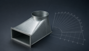
A square-to-round transition is a sheet metal fitting that connects a square or rectangular opening to a circular duct or collar. Unlike a straight duct section, its surface must change cross-sectional shape continuously over the height of the fitting — which is what makes flat pattern development more involved.
These fittings appear across a wide range of industrial applications:
- HVAC ductwork, connecting rectangular air-handling units or plenums to round supply or return duct runs
- Process exhaust and ventilation systems, linking square fan housings or equipment outlets to round ductwork
- Dust collection systems, transitioning from hopper or equipment outlets to round conveying lines
- Industrial hoods and enclosures, connecting custom rectangular openings to standard round exhaust ductwork
- Material-handling equipment, managing transitions between rectangular chutes and cylindrical pipes or tubes
The function in each case is the same: allow flow or material to pass from one cross-section geometry to the other through a fabricable, controlled form.
2.Start With the Right Design Inputs
A flat pattern is only as good as the inputs it was built from. Incomplete or ambiguous dimensions are the single most common cause of rework in square-to-round fabrication.
Before starting any layout work, confirm and document the following:
| Input | Notes |
|---|---|
| Rectangular base width | Finished inside or outside — confirm which |
| Rectangular base length | Finished inside or outside — confirm which |
| Round outlet diameter | Finished inside or outside — confirm which |
| Transition height | Vertical distance between the two profiles |
| Round outlet position | Center location relative to the rectangular base, not just diameter |
| Material | Mild steel, galvanized, stainless, aluminum, etc. |
| Material thickness | Required for allowance calculations and forming decisions |
| Joint and seam type | Lock seam, lap weld, butt weld, Pittsburgh seam, flanged edge |
| Connection details | How the transition connects to adjacent duct or equipment at each end |
Use finished dimensions, not nominal or assumed values — particularly when integrating with existing ductwork or equipment connections where tolerances have already accumulated.
2.1 Concentric vs. Eccentric Square-to-Round Transitions
The position of the round outlet relative to the rectangular base is one of the first things to establish, because it determines the geometry of the entire development.
| Comparison | Concentric | Eccentric |
|---|---|---|
| Outlet position | Centered on base | Offset to one side |
| Geometry | Symmetrical | Asymmetrical |
| True-length calculations | Many repeated lengths | More unique lengths |
| Layout complexity | Relatively simpler | More demanding |
| Typical use case | Centered duct connections | Offset equipment outlets, drainage considerations |
In a concentric transition, the center of the circular outlet aligns with the center of the rectangular base in plan view. The symmetric geometry means many generator lines share the same true length, simplifying the true-length schedule.
In an eccentric transition, the circular outlet is offset — sometimes in one direction, sometimes in two. Every generator line has a different length, and rigorous point-by-point tracking is required throughout the development.
Practical factors that determine the geometry include duct routing constraints, equipment connection position, drainage behavior in dust collection or exhaust applications, and service access requirements. Confirm the geometry before starting development — applying a concentric method to an eccentric transition produces a pattern that will not close correctly.
3. Choose a Fabrication Strategy Before You Lay Out the Pattern
The development approach should match how the part will actually be built. A flat pattern that is geometrically correct but incompatible with the shop’s equipment or joining method creates unnecessary rework.
1. Developed one-piece pattern A single continuous blank is developed, cut, and formed into shape, with the transition surface joined at one seam. This minimizes the number of weld seams. However, the surface of a square-to-round transition is not uniformly developable: the flat triangular areas between corners behave differently from the curved corner regions, and those corner areas require careful forming. One-piece development is generally more practical for smaller, lighter-gauge fittings with capable rolling equipment.
2. Multi-piece segmented construction The transition is divided into panels — most commonly four, each corresponding to one quadrant. Each panel is individually developed, cut, formed, and welded together. This approach suits heavier-gauge materials, press-brake fabrication shops, and situations where consistent, repeatable panels are more important than minimizing seam count. Four-piece construction is straightforward to inspect before assembly.
3. CAD/CAM-generated flat pattern Sheet-metal CAD tools can loft between the two profiles and unfold the result automatically. This suits shops with CNC cutting equipment, recurring orders, or complex eccentric geometries. Software-generated patterns require review: joint allowances, material thickness compensation, and manufacturability must be verified against actual tooling and process data — not assumed from default software settings.
Use this checklist to select the right approach:
- Order volume: One-off → manual triangulation; recurring → CAD/CAM with version control
- Material gauge: Light gauge → one-piece or multi-piece; heavy gauge → multi-piece pressed/welded
- Shop equipment: Press brake → multi-piece panels; plate roller → one-piece
- Seam requirements: Sealed or pressure-rated → minimize seams; standard ventilation → multi-piece acceptable
- Geometry: Symmetric concentric → any method; eccentric → CAD/CAM or careful manual triangulation
- Revision frequency: Repeating design → version-controlled CAD file; one-time build → documented manual layout
4. How to Develop a Square-to-Round Flat Pattern Using Triangulation
The triangulation method divides the transition surface into a series of triangles. Each triangle is a flat shape with measurable sides, so the three-dimensional surface can be reconstructed on a flat plate by laying those triangles out in sequence.
The central rule: every element line on the three-dimensional transition has a true length that is almost always longer than the same line appears in plan view. Using plan-view dimensions directly is the most common cause of a pattern that forms incorrectly or does not fit.
1. Create the Plan and Elevation Views
Begin with two orthographic views drawn to finished dimensions:
- Plan view (top view): Draw the rectangular base and position the circular outlet in its correct location. For a concentric transition, the circle sits centered on the rectangle. Label all four corners (A, B, C, D) and choose one corner as the seam reference. Mark the circle’s centerlines.
- Elevation view (front or side view): Draw the full transition height between the two profiles. This view provides the vertical height component used in true-length calculations.
Label everything clearly before proceeding. Consistent labeling across the plan view, elevation, true-length schedule, and flat pattern is what prevents numbering errors at later stages.
2. Divide and Number the Circular Profile
Divide the circular outlet into equal segments. The required number of divisions should be based on the specified dimensional tolerance, the fabrication method, and the acceptable roundness deviation — not assigned arbitrarily. As a general reference:
- 12 divisions: Basic approximation — suitable where a slightly faceted round end is within tolerance
- 24 divisions: Finer approximation — appropriate when roundness and end-connection fit are more critical
- 36 or more divisions: Near-true-curve — used for higher-precision requirements
More divisions improve the geometric approximation, but the final roundness of the formed part also depends on measuring accuracy, marking precision, cutting method, and forming capability — not on division count alone.
Number all division points in sequence — clockwise or counterclockwise — and carry that same sequence through every subsequent step. Reversing direction or restarting the sequence at any point produces a twisted or non-closing pattern.
3. Calculate the True Lengths
Each element line runs from a numbered point on the circular outlet to its corresponding connection point on the rectangular base. Its true length is the actual three-dimensional distance, resolved using:

Where:
- HH = transition height
- XX = horizontal distance between the two points in the X direction (plan view)
- YY = horizontal distance between the two points in the Y direction (plan view)
- LL = true length of the element line
Important: XX and YY are the coordinate differences between the specific circular division point and its corresponding base connection point — not the full width or length of the rectangular base.
Worked Example — Calculating True Lengths
Consider a concentric square-to-round transition with these dimensions:
| Parameter | Value |
|---|---|
| Rectangular base | 400 mm × 400 mm |
| Round outlet diameter | 200 mm (radius = 100 mm) |
| Transition height (H) | 300 mm |
| Divisions | 12 (every 30°) |
The rectangular base is centered at the origin. Corner A is at (200, 200). The circular outlet is also centered at the origin.
Locate the circular division points (12 equal divisions at 30° spacing):
| Point | Angle | X (mm) | Y (mm) |
|---|---|---|---|
| 1 | 0° | 100.0 | 0.0 |
| 2 | 30° | 86.6 | 50.0 |
| 3 | 60° | 50.0 | 86.6 |
| 4 | 90° | 0.0 | 100.0 |
| 5 | 120° | −50.0 | 86.6 |
| 6 | 150° | −86.6 | 50.0 |
| 7 | 180° | −100.0 | 0.0 |
Points 8–12 mirror Points 6–2 by symmetry for a concentric transition.

In this concentric, symmetric case Points 1 and 4 share the same true length to Corner A — as expected. For an eccentric transition with an offset outlet, these lengths would differ, and every element line must be calculated individually.
Build a complete true-length schedule before starting the flat layout. Carry full decimal precision through all intermediate calculations; round only when making the final transfer to the plate.
4. Construct the Developed Pattern
With the true-length schedule complete:
- Draw a baseline on the plate — this represents the seam edge and the starting reference.
- Mark the first step-off distance along the baseline. The chord length between two adjacent circular division points is 2rsin(π/n)2rsin(π/n), where rr is the outlet radius and nn is the number of divisions. For the example: 2×100×sin(15°)≈51.82×100×sin(15°)≈51.8 mm per division.
- Locate each new point by striking two intersecting arcs: one at the true length of the relevant element line from the known base corner; a second at the step-off distance from the previous circular point. Their intersection is the next point on the flat pattern.
- Continue in sequence — add one triangle at a time, each sharing one edge with the previous one, following the numbered sequence without deviation.
- Connect the boundary points when all triangles are complete. Base edges form straight lines; the circular edge is approximated by short chords between adjacent division points.
- Closure check: the final point must return to the starting reference position without a gap or overlap. Any mismatch indicates an error that must be resolved before cutting.
5. Add Allowances for the Actual Shop Process
The geometric development represents the theoretical finished surface. Before cutting, additional material must be added for every joint, seam, flange, and closure in the design.
Common allowances to evaluate:
| Allowance Type | Applies When |
|---|---|
| Weld preparation | Seams and end connections joined by welding |
| Lock seam or Pittsburgh seam | Mechanical HVAC seam closure |
| Lap joint overlap | Overlapping seam closure |
| Hem or folded edge | Edge stiffening or finishing |
| Connection flange | End connection to adjacent duct, collar, or equipment |
| Bend allowance / bend deduction | Press-braked flanges — value depends on material thickness, bend radius, material properties, and forming process |
No single allowance value applies universally. Values must follow the selected joint design, material thickness, equipment capability, and company fabrication standards.
Note that bend allowance for press-braked flanges is a separate calculation from the triangulation development. The geometric development gives the transition surface; flange allowances are added edges calculated from your tooling and the material’s actual neutral axis behavior. Do not combine the two without accounting for this distinction.
Before releasing the pattern, verify whether design dimensions refer to inside, outside, or centerline measurements. A mismatch of even one material thickness at each connection end can produce a visible installation error.
6. Turn the Development Into a Shop-Ready Drawing or CAD/CAM File
A flat pattern that exists only as a chalk line or a sketch is a single-use document. A revision, repeat order, or handoff to a different operator means redoing the entire layout. A documented drawing or CAD file converts the development into a controlled manufacturing asset.
A shop-ready release document should include:
- Revision identifier and date
- Material specification and nominal thickness
- Finished formed dimensions (square/rectangular opening, round diameter, height, offset if eccentric)
- Flat pattern dimensions with allowances clearly distinguished from geometric dimensions
- Seam and flange details with dimensions and joint type
- Bend or form direction callouts
- Welding notes (process, weld size, inspection class if applicable)
- Applicable dimensional tolerances
- Quantity per release
For CAD-generated developments, lofted sheet-metal models with unfolded flat patterns provide the strongest revision control. However, every automatically generated unfold requires review: bend allowance, K-factor, material thickness, and joint configuration must be set correctly for the output to match shop conditions. A software-generated pattern that has not been verified against real tooling and process data should not go to cut without a first-article check.
Nesting and cut orientation: for materials with a pronounced grain direction (certain stainless finishes, brushed aluminum), orient the pattern so the grain runs consistently across the visible face. Verify that an asymmetric pattern has not been mirror-reversed before cutting.
7. Form, Assemble, and Inspect the Transition
Cutting the flat pattern is the midpoint, not the endpoint. A part that leaves the cutting table dimensionally correct can still fail at assembly if forming, seam closure, and inspection are not handled systematically.
Forming sequence:
- Cut the flat pattern to the marked profile, including all allowances
- Prepare edges — deburr, grind, bevel for welding, or set up for mechanical seam closure as required
- Form the panels by rolling or press-brake bending, depending on the fabrication method and gauge
- Assemble the seams by tack welding, lock-forming, or clinching before completing final joints
- Install flanges or connection collars at both ends if required
First-article inspection checklist:
Before releasing any quantity, inspect the first completed part against all drawing dimensions:
- Rectangular opening dimensions in both directions
- Round outlet diameter — measure at multiple orientations and check for roundness deviation, not just a single diameter
- Transition height
- Offset position of the round outlet (eccentric transitions)
- Seam closure — no visible gap, twist, or excess overlap
- Flange flatness and connection alignment
- Absence of visible distortion or angular deviation
Fit-up check: Hold the transition against the actual mating duct sections or equipment interfaces before approving the batch. Drawing dimensions confirm the geometry; fit-up against the real installation confirms that accumulated tolerances across the full system are within range.
If first-article problems appear, trace each observation back to its most likely upstream source:
8. Common Square-to-Round Development Problems and How to Avoid Them
Unequal circle divisions Inconsistent spacing accumulates across the full development. Even small errors produce a noticeably irregular round end. Verify all divisions are equal before numbering them.
Incorrect point sequence The numbering from the circular outlet must carry through the plan view, true-length schedule, and flat pattern without reversal or restart. Swapping two points introduces a twist that cannot be corrected by forming.
Using projected dimensions instead of true lengths A line measured in plan view is shorter than the actual inclined element line. The error compounds across every triangle in the development. Resolve every element line to its true length before transferring it to the plate.
Missing or misidentified allowances The geometric pattern represents the finished surface with no extra material. Every seam closure, weld edge, and flange must be added explicitly. Map each allowance to its specific joint location before cutting.
Ignoring material thickness For heavier-gauge or close-tolerance parts, the inside-versus-outside dimension difference is meaningful. Bend allowance for press-braked flanges depends on material thickness, bend radius, and material forming behavior — not a fixed rule of thumb.
Skipping the first-article check A pattern error caught on the first part costs almost nothing to correct. The same error across a production run generates scrap that is significantly more expensive to address.
9. Manual Layout vs. CAD/CAM Automation: Which Is Right for Your Shop?
Both approaches produce accurate square-to-round flat patterns when applied correctly. The right choice depends on production context.
Manual triangulation is appropriate when:
- The part is a one-off or very-low-volume fitting that does not justify digital setup
- Experienced layout personnel are available and working to an established procedure
- Field modification or on-site layout is required
- No CNC cutting equipment is available to take advantage of a digital file
- The geometry is straightforward and concentric
CAD/CAM or dedicated development tools are the better fit when:
- The same or similar geometry recurs across multiple orders
- Eccentric or complex offset geometry increases the risk of manual error
- CNC cutting equipment can consume the flat pattern directly as a cut file
- Drawing revisions must propagate automatically to the flat pattern
- Production volume makes manual marking and layout a throughput bottleneck
The factor that matters most in practice is the cost of rework relative to the cost of the digital process. A single miscut on heavy stainless plate can justify a CAD-generated pattern for that one job. A recurring catalog fitting almost always benefits from a locked, versioned file regardless of geometry complexity.
One principle applies regardless of method: no flat pattern should go to cut without a check against the confirmed design inputs, and no production quantity should be released without a first-article inspection.
9.1 When to Move from Manual Layout to Automated Duct Fabrication
For shops producing square-to-round transitions on a regular basis, repeated manual layout and marking becomes a production constraint. The signs that automated duct fabrication equipment may offer a better workflow include:
- Frequent repeat orders for the same or similar transition geometries
- High variation in fitting dimensions requiring a new layout for every job
- Cutting and marking accuracy limiting first-pass yield
- Need for integrated cutting and forming workflows on the same production run
- Documentation and revision control requirements that manual layouts cannot easily support
Evaluating the move from manual to automated development is as much a production efficiency question as a technology decision. The starting point is identifying where in the current layout-to-fabrication process most of the rework time and material cost originates.
10. FAQ
Answer: Rectangular base width and length, round outlet diameter, transition height, and the position of the round outlet center relative to the rectangular base. Material, thickness, and joint type are also required before allowances can be finalized. All dimensions should be confirmed as finished values — inside, outside, or centerline — before development begins.
Answer: In a concentric transition, the round outlet center aligns with the rectangular base center in plan view, producing symmetric geometry where many element lines share the same true length. In an eccentric transition, the outlet is offset, producing unique true lengths for most or all element lines and requiring more rigorous point tracking throughout the layout.

Answer: The number depends on the specified dimensional tolerance, fabrication method, and acceptable roundness deviation. Twelve divisions are a common starting point for general ductwork; 24 are appropriate when a closer approximation of the circular profile is required. More divisions improve the geometric approximation, but the final roundness of the formed part also depends on measuring, cutting, and forming accuracy.
Answer: Yes. Sheet-metal CAD tools can loft between the two profiles and unfold the result into a flat pattern. The output is reliable only when bend allowance, K-factor, material thickness, and joint configuration are set correctly for the actual process. Automatically generated patterns must be reviewed for manufacturability and dimensional accuracy before release to cut.
Answer: Verify that the developed pattern closes — the final construction point should return to the starting reference without a gap or overlap. Confirm that all allowances are added and correctly located. Check that the pattern dimensions match the confirmed design inputs. Cut and inspect one part before releasing any production quantity.
Answer: Yes. The triangulation method produces a fully defined flat pattern from the input dimensions: rectangular base size, round outlet diameter, transition height, and outlet position. CAD/CAM tools and dedicated sheet-metal development calculators can automate this process, outputting the pattern as a DXF, PDF, or SVG file ready for CNC cutting or manual transfer to the plate. In either case, the geometry is determined entirely by the input dimensions and the chosen number of circle divisions.
11.Treat the Flat Pattern as a Controlled Manufacturing Document
A correctly developed square-to-round flat pattern starts with verified inputs, applies a development method matched to the geometry and the shop, resolves all element lines to their true lengths, adds process-specific allowances, and closes with a first-article inspection before production quantities are released.
Accurate, repeatable fabrication comes from treating the flat pattern as a controlled document: dimensioned, reviewed, versioned, and validated against a physical part. That applies equally to a manually constructed triangulation layout and to a CAD/CAM-generated cut file.
For shops that produce square-to-round transitions regularly, a standardized duct transition fabrication checklist that records input confirmation, allowance decisions, inspection results, and revision history makes it practical to reproduce accurate results when an order repeats — and to identify where errors originated when they do not.