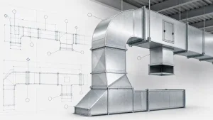
HVAC duct shop drawings are the contractor- and fabricator-level documents that convert an approved HVAC design into buildable ductwork. They define what gets manufactured, where it goes, how it connects, and what must remain accessible—before a single sheet of metal is cut.
On straightforward projects, a modest drawing package may be sufficient. On complex commercial, healthcare, data center, or industrial work, the shop drawing set is a production-control document that determines whether ductwork fabricates correctly, installs without field modification, and performs as the engineer specified.
This guide covers what a fabrication-ready duct shop drawing must include, how to read one, what to verify before releasing to the shop, and how to avoid the failures that most commonly result in rework.
1.Design Drawings vs. Duct Shop Drawings: What Changes Before Fabrication
A design drawing communicates the engineer’s intent. A duct shop drawing resolves that intent into something a fabricator can manufacture and a crew can install.
Design drawings typically establish duct routing and approximate sizing, system configuration, airflow quantities and pressure requirements, equipment selections and basic connections, and code-required features such as fire/smoke dampers and access provisions.
What they do not define—and what the ductwork shop drawing must resolve—includes:
- Actual duct elevations accounting for structure, other services, and ceiling constraints
- Fitting geometry: elbows, offsets, transitions, reducers, and takeoffs with full dimensions
- Joint and seam systems selected for the applicable pressure class
- Reinforcement based on duct size and pressure classification
- Insulation thickness as physical clearance, not just a specification note
- Support and hanger locations
- Piece identification, break points, and installation sequence
- Access clearance zones for VAV boxes, dampers, controls, and equipment
The gap between these two levels is where rework originates. A route that works on a design drawing may not fit once flanges, insulation, hangers, and adjacent services occupy their actual space.
1.1 The Questions a Fabrication-Ready Drawing Must Answer
A quick test before releasing any duct section:
- What is being made? Shape, dimensions, material, gauge, joint and seam system, fittings, and quantity.
- Where does it go? Coordinate location, elevation, orientation, and relationship to reference points and structure.
- How does it connect? Adjacent pieces, equipment connections, takeoffs, flexible connections, and support method.
- What must stay accessible? Damper operators, VAV controllers, test-and-balance ports, clean-out access, and equipment service clearances.
- Which revision governs? Current revision tied to resolved RFIs, coordination decisions, and approvals.
Any open question should become a documented RFI or coordination action before the drawing is released. Undocumented assumptions made at the fabrication stage routinely become change orders at the installation stage.
2.Start with Complete Inputs and Clear Responsibilities
Detailing that begins from incomplete or outdated information produces drawings that require continuous revision. Establishing what is needed—and who owns which decisions—before detailed drafting begins prevents most preventable rework.
Required source information typically includes:
- Current architectural, structural, and reflected ceiling plans
- Latest mechanical design drawings and specifications
- Electrical, plumbing, fire protection, and low-voltage routing plans
- Equipment submittals confirming connection sizes and service clearances
- Project specifications covering pressure/construction class, insulation, and applicable standards
Project-specific requirements to confirm early:
- SMACNA construction class for each duct service (SMACNA’s HVAC Duct Construction Standards provides construction class definitions and associated gauge, reinforcement, and joint requirements; always verify against the current edition and project specification)
- Insulation type and thickness: external wrap, internal liner, or double-wall construction
- Fire-rated duct, smoke control, or seismic bracing requirements
- Coordination rules: BIM model authoring, clash tolerance, revision workflow, and submittal format
- Commissioning and balancing access requirements
Where projects involve UK or European specifications, relevant standards such as BSRIA and HVCA/DW/144 apply in place of or alongside SMACNA. Requirements for duct gauge, joint type, and leakage class differ between standards and must be confirmed against the project’s governing documents before detailing begins.
Responsibility map:
| Role | Responsibility |
|---|---|
| Design engineer | Design intent, system performance, pressure class, code compliance |
| Sheet metal detailer | Coordinated buildable geometry, fitting design, piece marks, release packages |
| Fabricator | Production conventions, joint/seam confirmation, material procurement |
| Field superintendent | Installation sequence, access constraints, field-condition verification |
| Project/construction management | Conflict resolution, RFI management, approved revision control |
When ownership is unclear, coordination conflicts accumulate quietly until they produce a field problem.
2.1 Existing Buildings Require Field Verification
On retrofit and renovation projects, record drawings are a starting point, not a reliable source of truth. Concealed conditions, prior modifications, access restrictions, and structural changes routinely differ from what the drawings show.
Before finalizing routing on existing buildings:
- Visit the site to verify ceiling height, structural clearances, and available pathways
- Identify obstructions not captured in drawings: conduit bundles, piping, structural reinforcement, or undefined equipment
- Establish accurate control points so duct locations can be dimensioned reliably
- Photograph or sketch complex conditions where routing decisions need to be documented before detailing proceeds
For large-scale retrofits, laser scanning or measured survey can provide the accurate existing-condition model that prevents conflicts after fabrication.
3. Building a Coordinated Duct Route
Detailing individual duct sections before the overall route is coordinated is one of the most consistent sources of rework on complex projects. Coordination belongs ahead of detail drafting.
The coordination phase establishes where each duct service runs in three dimensions, that ceiling zones, shaft clearances, and equipment service spaces are protected, and that insulation, flanges, hangers, and required clearances are physically modeled—not approximated in text notes.
BIM coordination tools are appropriate when space is congested, multiple trades share tight ceiling zones, or prefabrication requires high dimensional certainty. On straightforward projects, a well-managed 2D coordination process with documented decisions and distributed marked-up drawings is often equally effective. The tool does not determine quality; the process does.
3.1 Resolve Clashes by Impact, Not Just Geometry
Clash detection reviews generate lists of conflicts. Not all carry the same consequence.
Prioritize resolution in this order:
- Code compliance and life-safety conflicts: Fire-rated duct penetrations, smoke damper locations, seismic bracing interference, and evacuation path restrictions.
- Equipment serviceability: Access zones for fire/smoke dampers, VAV boxes, AHU coils, test ports, and controls that cannot be corrected after ceilings are closed.
- Major duct mains and primary routing conflicts: Changes here affect multiple downstream pieces and fabrication packages.
- Minor branches and connections: Minor branch conflicts may be easier to resolve than main-duct conflicts, but affected pieces should remain on hold until the required changes are coordinated, documented, and approved. Unaffected portions of a package may proceed only when the release boundaries are clearly defined.
When a conflict is resolved, document the decision: what changed, which trades agreed, who approved it, and how it was incorporated into the revised drawing.
4. Preserving HVAC Performance During Coordination
Coordination often introduces changes that affect more than geometry. An offset added to avoid a structural beam, a reduced ceiling height that forces a duct size change, or a transition relocated to fit available space can affect pressure loss, airflow distribution, noise, and system balance.
Fitting geometry affects pressure loss and airflow distribution. Where space permits, appropriately designed radius elbows may reduce pressure loss compared with less favorable elbow configurations. Transition geometry should be selected according to airflow requirements, available clearance, and the applicable design criteria—not based on a single general rule.
Changes that materially affect design-level assumptions—main duct reductions, significantly extended routes, removed balancing points—should be flagged to the mechanical engineer for review. Revising geometry without engineering sign-off can invalidate system performance in ways that are not visible until commissioning.
5. What a Fabrication-Ready HVAC Duct Shop Drawing Should Include
The following content is organized by the three operational purposes a complete HVAC fabrication drawing set must serve: locating the system, manufacturing the components, and guiding installation.
Note: Final material gauges, reinforcement, joint systems, and sealing requirements must be verified against the applicable construction standard (such as SMACNA), pressure class, material specification, and project documents. The items listed below reflect typical content requirements; specific values and configurations are governed by project-level criteria.
5.1 Layout and Coordination Information
- Plan views with duct centerlines, sizes, routing, and dimensions from reference points or column grids
- Elevation or section views confirming top and bottom of duct, insulation envelope, and minimum ceiling clearances
- Airflow direction indicators
- Equipment interfaces: AHU, FCU, VAV box, and diffuser/grille connections with applicable neck sizes
- Branch connections, takeoffs, and main-to-branch transition locations
- Wall and floor penetrations with fire-stopping scope noted where applicable
- Locations of all accessory components: fire dampers, smoke dampers, volume control dampers, VAV boxes, test-and-balance dampers, and associated access requirements
- Service clearance zones maintained as reserved physical space in the model or drawing
5.2 Fabrication and Assembly Information
- Duct shape, dimensions, and pressure/construction class
- Material: galvanized steel in most commercial applications; stainless steel or aluminum where environment, hygiene, or weight requirements apply
- Sheet gauge per the applicable construction standard for the duct size, pressure rating, and project specification
- Joint and seam system appropriate to the pressure class and duct size: TDC/TDF flange, angle-iron flange, S-clip, Pittsburgh seam, button punch, snap-lock, or other specified system
- Reinforcement method and spacing per the applicable construction class and duct dimensions
- Fitting geometry: elbow radius, turning vane requirements, transition type, reducer configuration, and direction of offset for asymmetric fittings
- Insulation: type, thickness specified as physical clearance—not just a note
- Piece marks, joint lengths, cut lengths, and quantities
- Sealing requirements appropriate to the pressure class
5.3 Installation and Inspection Information
- Hanger and support locations consistent with applicable standards for the duct size, weight, and pressure class
- Installation sequence for areas where duct must be erected before adjacent trades or ceiling systems close the access window
- Piece identification matching fabrication marks
- Access door type, size, and opening direction confirmed to work in the installed condition
- Penetration details, fire-stopping interface, and sleeve requirements where applicable
- Test ports and balancing damper locations accessible for commissioning
6.How to Read an HVAC Duct Shop Drawing: A Fabrication Detail Example
Understanding what belongs on a shop drawing is easier with a concrete example. The following walkthrough describes a typical rectangular duct section at a VAV box takeoff—a common and well-documented detail type in commercial HVAC ductwork systems.
6.1 Plan View: What It Shows and Why
The plan view locates the duct in the building. In a standard rectangular duct plan detail, you would typically see:
- Duct size label: For example, 24″ × 12″, indicating width × height. Size changes at transitions are labeled at both ends.
- Centerline and routing: The duct centerline is drawn relative to column grids or wall references, not floating in space. A typical note might read: CL duct 3′-6″ from grid A.
- Takeoff to VAV box: The branch connection from the main trunk is shown with the branch duct size, takeoff fitting type (45° entry, conical, or square entry), and the VAV box neck size from the submittal.
- Elevation call-out: BOD 9′-10″ (bottom of duct) referenced from finished floor, allowing the installer to set hanger heights before the ceiling grid is installed.
- Insulation note: External 1″ rigid wrap or 1-1/2″ flexible wrap, shown as a dashed boundary around the duct. This dashed line is the physical clearance that must clear adjacent trades—not the duct face.
- Access door symbol: Shown adjacent to the VAV box with a note indicating door size, typically 12″ × 12″ or as specified, and the opening direction confirmed to clear the ceiling grid and adjacent conduit.
6.2 Section View: What the Plan Cannot Show
The section view—usually cut at the VAV box or at a fitting—shows what the plan view compresses into a single line.
A section through a main-to-branch transition typically shows:
- Top and bottom of duct elevations for both the main and branch, with the offset geometry dimensioned
- Flange depth on both sides of the joint, confirming the physical gap between duct faces and how much clearance the insulation and flange consume
- Structural clearance: The nearest beam face labeled, with the distance from the top of duct (including insulation) to the beam confirmed
- Ceiling grid position: Typically shown as a dashed reference line at the bottom, confirming the VAV box access door is reachable from below
Without a section view, the installer cannot confirm whether the duct physically fits at the transition, whether the access door clears the ceiling, or whether the insulation envelope encroaches on the beam.
6.3 Piece Mark and Fabrication Schedule
Each distinct duct section and fitting carries a piece mark that appears on the drawing, the fabrication order, the packaging label, and the installation drawing. A simplified fabrication schedule for a small duct package might look like this:
| Piece Mark | Description | Size (W × H) | Length / Qty | Material | Gauge | Joint System |
|---|---|---|---|---|---|---|
| D-01 | Rectangular duct | 24″ × 12″ | 7′-4″ / 1 | Galv. steel | Per spec | TDC flange |
| D-02 | Rectangular duct | 24″ × 12″ | 5′-9″ / 2 | Galv. steel | Per spec | TDC flange |
| F-01 | 45° branch takeoff | 24″×12″ → 10″×8″ | — / 1 | Galv. steel | Per spec | TDC / slip |
| F-02 | Eccentric reducer | 24″×12″ → 18″×12″ | — / 1 | Galv. steel | Per spec | TDC flange |
| F-03 | Square throat elbow | 12″ × 12″ | — / 1 | Galv. steel | Per spec | TDC flange |
Gauge, reinforcement, and sealing requirements must be confirmed against the applicable SMACNA construction class and project specification for each duct size and pressure class. The schedule above illustrates format only.
The piece mark system allows the fabricator to cross-reference each row against the drawing, the installer to identify and sequence pieces on site, and the project team to track revisions—if D-01 is revised, the new revision replaces D-01 in the schedule, and all previously fabricated pieces with the old mark are flagged for review.
This is where the connection between drawing accuracy, fabrication control, and installation efficiency is most direct. A missing piece mark, an incorrect length, or an unresolved fitting orientation in this schedule propagates into cut material before anyone on site notices.
7. Review Before Release: A Fabrication-Readiness Checklist
A controlled release gate—even an informal one—prevents the most costly shop drawing failures. Complete the following five checks before any duct section or package is released to fabrication.
1. Design intent
- Duct sizes match approved mechanical drawings or documented revisions
- Airflow quantities preserved at all supply, return, and exhaust points
- Pressure class and construction requirements correctly applied
- Equipment connections match confirmed submittal dimensions
2. Coordination
- No unresolved geometry clashes with structure, electrical, plumbing, or fire protection
- Required clearances maintained around all access-required components
- Ceiling and shaft constraints verified against current architectural information
- Penetrations and fire-stopping scope coordinated with affected trades
3. Constructability
- Fittings are buildable by the fabrication shop and installable in the available space
- Insulation, flanges, and hangers have physical clearance verified in plan and section
- Break points and piece lengths are practical for transport, rigging, and installation
- Installation sequence is feasible given other trade activities
4. Fabrication detail
- All pieces are fully dimensioned and piece-marked
- Joint systems, gauges, reinforcement, and sealing are specified per the applicable standard and project documents
- Fitting geometry and orientation are unambiguous
- Quantities match the drawing
5. Revision control
- All required reviews and approvals are documented and complete
- Open RFIs and coordination assumptions are resolved or formally managed before release
- Drawing revision designation matches the released package
8. Common Duct Shop Drawing Failures—and How to Prevent Them
Most field problems traced back to duct detailing errors fall into a small number of recurring patterns.
8.1Working from outdated backgrounds
Design drawings are revised throughout the project. Shop drawings prepared from superseded backgrounds may route ductwork into space now occupied by structural changes, relocated equipment, or different ceiling heights.
Prevention: Confirm the background revision level before detailing begins and again before release. Record the source document revision on the drawing.
8.2 Coordinating centerlines but ignoring physical space
A duct that fits in the model at centerline may not fit once insulation, flanges, hanger rods, and access clearances are included. This is particularly common where multiple services run in the same direction or tight turns bring flanges close together.
Prevention: Verify the full physical envelope—not just the centerline—before the route is finalized.
8.3 Omitting fitting orientation and elevation references
A transition can be installed with either side flat, concentric, or eccentric. A duct offset can drop vertically or shift horizontally. When the drawing does not specify orientation, field crews choose, and the choice may conflict with support locations, adjacent services, or maintenance access.
Prevention: Show orientation explicitly on all fittings where it affects fit-up, clearance, or performance. Use section views to confirm elevation and orientation together.
8.4 Placing dampers or equipment where service access is blocked
Fire dampers tucked above fixed ceilings, VAV controllers behind cable trays, and actuators recessed into structure are among the most common access failures. They produce expensive remedial work after ceilings close.
Prevention: Check every access-required component against the physical installed condition. Confirm door swing and clearance in section view, not just in plan.
8.5 Releasing sections with open coordination decisions
When a drawing is released while a conflict or RFI is unresolved, the fabricated piece often requires field modification. The cost of one change order typically exceeds the cost of holding the release until the conflict is resolved.
Prevention: Treat unresolved coordination issues as a formal hold condition, not a deferred task.
9.From Approved Drawing to Fabrication and Field Installation
An approved drawing is not the end of the process. How information moves from approval to fabricated piece to installed system determines whether careful detailing work actually reaches the field.
9.1 Shop release and production
Release packages should identify piece marks, quantities, priority sequence, and applicable revision. Where fabrication software interfaces directly with cutting or forming equipment—a common arrangement on automated duct fabrication lines —the release data format must be verified for compatibility before the first production run.
9.2 Packaging and delivery sequence
Duct sections should be labeled and delivered in installation sequence where practical. Large or complex sections that require pre-rigging or early installation—main trunks, risers, mechanical room connections—should be identified and prioritized. Delivering pieces out of sequence increases handling problems and the risk of incorrect installation.
9.3 Managing field changes and as-built documentation
Site conditions occasionally require field modifications. Every modification affecting duct geometry, support, or performance should be captured in a controlled revision and communicated back to the drawing record. Undocumented field changes create as-built conditions that differ from the drawings, causing problems for commissioning, maintenance, and future modifications.
When construction is complete, drawings should be updated to reflect the actual installed configuration. As-built duct shop drawings give the facility’s operations team an accurate record of what is in place—including damper locations, access points, and connection details no longer visible after ceilings are finished.
10.When to Use Coordinated BIM vs. 2D Duct Shop Drawings
Not every project requires a fully coordinated BIM model. Matching the detailing approach to the project’s actual complexity avoids spending coordination budget where it does not reduce risk.
| Factor | 2D Approach Appropriate | Coordinated BIM Appropriate |
|---|---|---|
| Ceiling space | Open, low-density | Congested, multiple trades |
| Coordination risk | Limited MEP conflict potential | Dense MEP, tight clearances |
| Fabrication volume | Small quantities, simple shapes | High volume, complex fittings, prefabrication |
| Project requirements | No BIM mandate | Owner or specification requires model |
| Revision frequency | Stable design | Frequent changes requiring model updates |
| Commissioning risk | Straightforward system balance | Complex zoning, critical airflow paths |
The decision should be based on where coordination failures are most likely and what the cost of field modification would be relative to upfront coordination investment. For high-volume MEP coordination drawings on complex commercial projects, the investment in BIM coordination typically recovers through reduced RFIs and change orders.
11. Selecting an HVAC Duct Shop Drawing Partner or Building an Internal Workflow
For contractors evaluating an outsourced detailing or BIM coordination service, deliverable quality depends on more than software capability.
Evaluation criteria:
- Sector experience: Healthcare, data centers, industrial facilities, and high-rise commercial work each have distinct coordination and code requirements. General MEP experience is not equivalent.
- Fabrication knowledge: A detailing team that understands sheet-metal production—joint systems, seam types, coil widths, piece-mark conventions—produces drawings that fabricate without interpretation problems.
- Coordination process: Ask how clashes are prioritized, documented, and resolved. A clear process matters more than a high clash count.
- QA review gates: Independent review before release catches errors that the detailer who drew the package may overlook.
- Revision management: Confirm how drawing revisions are tracked, communicated, and controlled across the project lifecycle.
- Deliverable compatibility: Drawings must be usable by the fabrication shop’s production software and by the installation team.
When evaluating a prospective partner, request a representative sample package—not marketing renderings. A useful sample shows plans, sections, fitting details, piece marks, revision tracking, and coordination documentation.
For contractors building an internal HVAC shop drawing detailing workflow, establishing a documented process for inputs, coordination, release authorization, and revision control is more effective than investing in software alone.
12. FAQ: HVAC Duct Shop Drawings
Q1: What is the difference between an HVAC design drawing and a duct shop drawing?
Answer: A design drawing communicates the engineer’s system intent—routing, sizing, pressure class, and equipment selection. A duct shop drawing resolves that intent into fabrication and installation instructions: fitting geometry, joint systems, piece marks, elevations, reinforcement, access provisions, and installation sequence. Design drawings are not fabrication-ready; shop drawings are.
Q2: Who prepares HVAC duct shop drawings?
Answer: Sheet-metal contractors, duct fabricators, and MEP detailing firms prepare shop drawings from design documents issued by the mechanical engineer. On BIM-coordinated projects, a dedicated detailing or coordination team—in-house or outsourced—typically leads the process.
Q3: What details make a duct shop drawing fabrication-ready?
Answer: Full dimensions and elevations, fitting geometry with orientation specified, pressure/construction class and gauge per the applicable standard and project specification, joint and seam system, reinforcement, insulation clearance, piece marks, hanger locations, access door placement confirmed in section view, and a resolved revision status with no open coordination holds.
Q4: When should a contractor use BIM coordination for ductwork?
Answer: When ceiling space is congested, multiple trades share tight zones, fabrication volumes are high, prefabrication is planned, or project specifications require a model. For simple, low-density work with limited MEP conflict potential, well-managed 2D coordination is often sufficient.
Q5: How do duct shop drawings reduce field rework?
Answer: By resolving conflicts, dimensions, fittings, and access requirements before fabrication begins. When ductwork is manufactured to correct dimensions with confirmed clearances and routing, field modifications become the exception rather than a routine cost.
Q6: What should be verified before ductwork is released to fabrication?
Answer: Design intent, coordination (no unresolved clashes or open RFIs), constructability, fabrication detail completeness, and revision control. If any check is unresolved, the affected pieces should remain on hold until the issue is documented and closed.
Q7: How are shop drawings handled on retrofit projects?
Answer: Field verification is required before finalizing routing. Record drawings are a starting point, but existing conditions—actual ceiling heights, concealed obstructions, and prior modifications—must be physically confirmed. Sketch documentation, photographs, or laser scanning may be used to capture existing conditions accurately.
13. Treating Shop Drawings as a Production-Control Document
Effective HVAC duct shop drawings protect design intent, give the fabrication shop unambiguous manufacturing instructions, and give the installation crew accurate field guidance. The real value is in what they prevent: field modifications, change orders, damaged material, installation delays, and systems that do not commission as specified.
The fabrication-readiness checklist in this article—covering design intent, coordination, constructability, fabrication detail, and revision control—provides a practical starting point for any release review process.
For facilities producing ductwork at volume, the connection between drawing quality and production efficiency is direct. Accurate piece marks, confirmed fitting geometry, and resolved coordination reduce setup time, minimize material waste, and shorten the gap between approved drawing and installed system. For more on how fabrication data flows from shop drawings into production, see HVAC ductwork pressure classes and construction standards.