1. Introduction
HVAC duct drawings are the roadmap between a system’s design and the ductwork that actually gets built. Whether you are estimating a job, coordinating an install, or preparing sheet metal for fabrication, reading these drawings correctly is what keeps a project on time, on budget, and free of expensive rework.
This guide breaks down how to read HVAC duct drawings the way a fabricator does — starting with drawing types and symbols, then moving through duct sizes, elevations, fittings, and schedules, and finishing with a practical checklist you can use before any duct goes into production.
2. Understanding HVAC Drawings
HVAC drawings are mechanical drawings that show how air, and sometimes water and refrigerant, move through a building. They tell you what equipment is installed, where the ductwork runs, how big each duct is, and how every component connects.
Reading them is less about memorizing symbols and more about knowing the order to check things: confirm which drawing you are holding, read the legend, trace the airflow, then pull the details you need for your task.
Before you rely on any sheet, check the title block — project name, sheet number, date, and especially the revision number. Working from an outdated revision is one of the fastest ways to fabricate the wrong duct.
3. HVAC Drawing Types
A mechanical set contains several drawing types, and each one serves a different purpose. Knowing the difference tells you which sheet is safe to fabricate from and which is only for understanding intent.
3.1 Floor Plans
Floor plans are the primary working drawings. They show ductwork and equipment in top-down (plan) view on each floor, with duct sizes noted along each run. They are ideal for understanding routing, but they rarely show enough detail on their own for fabrication.
3.2 Shop Drawings
Shop drawings are the coordinated version of the design — adjusted to fit around structure, ceilings, and other trades before work begins. They resolve conflicts and reflect approved changes, which makes them far more reliable than the base design plan.
3.3 Fabrication Drawings
Fabrication drawings define ductwork at the component level: exact dimensions, materials, gauges, joint types, reinforcement, and accessories. These are the drawings that carry the information a shop actually needs to cut and form duct.
3.4 Sections and Details
Sections and details show what a plan view cannot — vertical clearances, how ducts stack around beams, transition direction, and how connections are built. Always check the referenced detail before assuming the geometry of a fitting.
4. Symbols and Legends
Every drawing set has its own legend, and it is the single most important page to read first. Symbols, abbreviations, and line styles can vary between projects, so never assume a symbol means the same thing on every job.
4.1 Common HVAC Abbreviations
You will see these abbreviations on almost every set:
| Abbreviation | Meaning |
|---|---|
| SA | Supply Air |
| RA | Return Air |
| OA | Outside Air |
| EA | Exhaust Air |
| FD | Fire Damper |
| SD | Smoke Damper |
| VD | Volume Damper |
| VAV | Variable Air Volume Box |
| AFF | Above Finished Floor |
4.2 Airflow Symbols
Airflow is usually shown with arrows and line styles. As a common convention, supply air is drawn with solid lines and return or exhaust air with dashed lines — but always confirm against the project legend before relying on it.
4.3 Ductwork Symbols
Ductwork symbols identify duct runs, transitions, dampers, turning vanes, flexible connections, diffusers, and grilles. Each terminal or accessory usually carries a tag that cross-references a schedule for its full specification. Common accessories such as dampers, turning vanes, flexible connections each add pieces and inspection points to a job.
5. Reading Ductwork Layouts
Once you understand the symbols, read the layout by following the air — not by jumping from duct to duct.
5.1 Supply, Return, and Exhaust Air
Start at the air handler, rooftop unit, or fan, then trace the supply path out to the diffusers and the return/exhaust path back. Tracing airflow this way makes sure you don’t miss a branch, a transition, or a fitting.
5.2 Duct Sizes
Rectangular duct is noted as width × height; round duct is noted by diameter. Keep in mind that a size callout alone does not tell you the material, gauge, pressure class, or fitting length — those come from the schedules, notes, and details.
5.3 Duct Elevations
Elevation tells you whether a duct actually fits. Check whether the drawing references bottom-of-duct, top-of-duct, or centerline, and verify it against ceiling height and structure. The same duct size can require a very different offset depending on its elevation.
5.4 Duct Fittings
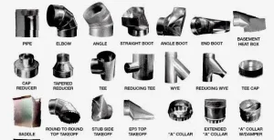
Elbows, reducers, tees, offsets, and transitions are where most fabrication complexity lives. Plan view can hide vertical movement and turning-vane requirements, so confirm each fitting against its section or detail.
6. Equipment Schedules
Schedules are the backbone of the documentation. Each tagged item on the plan (for example AHU-1 or EF-3) points to a row in the schedule that lists its full specification — airflow (CFM), capacity, connection sizes, electrical data, weight, and dimensions.
Always cross-check the tag on the plan against the schedule before ordering or fabricating anything. Diffuser and grille schedules work the same way, defining neck size, type, finish, and design airflow for each terminal.
7. Duct Details and Connections
This is where reading turns into real fabrication decisions.
7.1 Duct Joints
Drawings and specifications define how duct sections connect — for example TDF/TDC flanges, slip-and-drive, angle-iron flanges, or Pittsburgh lock seams. The specified joint determines the forming, locking, and assembly steps in the shop.
7.2 Dampers and Access Doors
Look for volume dampers, fire and smoke dampers, and access doors. These are frequently required at rated walls and floors, and each one adds pieces, accessories, and inspection points to the production package.
7.2 Reinforcement and Sealing
Higher-pressure duct often requires reinforcement (stiffeners, cross-breaking, tie rods) and a specified sealant or leakage class. Confirm these requirements from the duct schedule and specifications, not from the plan view alone.
8. Coordinating HVAC Drawings
A duct that reads perfectly on the mechanical sheet can still fail on site if it clashes with another trade. Coordinate before you release anything to production.
8.1 Ceiling Plans
Compare diffuser and grille locations against the reflected ceiling plan (RCP). Misalignment between the HVAC plan and the RCP is one of the most common field conflicts, causing clashes with lights, sprinkler heads, and ceiling grid.
8.2 Structural Drawings
Check duct routing against beams, joists, deck, and shafts. Structural clearances often force offsets and transitions that must be reflected in fabrication.
8.3 Other MEP Systems
Confirm the duct route against piping, cable trays, sprinklers, and electrical containment, and leave room for equipment service access.
9. Preparing Ductwork for Fabrication
Once the drawings are read and coordinated, the goal is to turn approved information into a clean production package.
9.1 Material and Gauge
Confirm the material, thickness/gauge, coating, and any pressure-related construction requirements for each run before selecting coil or sheet stock.
9.2 Drawing Revisions
Verify you are fabricating from the current released revision. Check revision clouds and revision logs, and never release production from an obsolete or unapproved set.
9.3 Production Checklist
Run through a quick check before any duct goes to the line:
- Current released revision confirmed
- Legend, notes, and duct specs reviewed
- Every duct segment has size, shape, system, and location
- Materials, gauge, and joints defined
- Elevations, offsets, risers, and details checked
- Dampers, access doors, liners, and accessories included
- Conflicts documented and clarified
- Piece IDs, labels, and inspection points ready
With a verified package like this, an auto duct line or duct station can run consistent, repeatable cutting, forming, and flanging — because the data feeding the machine is accurate.
10. Common HVAC Drawing Mistakes
Avoid the errors that most often cause rework:
- Fabricating from an outdated revision.
- Treating the floor plan as the only source of truth.
- Assuming a symbol without checking the project legend.
- Reading duct size without confirming elevation.
- Missing a referenced fitting detail.
- Using a schedule without cross-checking the plan tag.
- Confusing design intent with released fabrication data.
- Leaving accessories (dampers, access doors, flex connectors) out of the package.
11. FAQ
A shop drawing coordinates the proposed installation around structure and other trades. A fabrication drawing goes further, defining component-level dimensions, materials, joints, and reinforcement needed to actually build the duct.
Usually not. Floor plans show routing and sizes, but you still need sections, details, schedules, and specifications to confirm elevation, material, gauge, joints, and fittings.
Rectangular duct is width × height and round duct is by diameter. Elevation notes reference bottom-, top-, or centerline-of-duct; always verify against ceiling height and structure.
No. Common abbreviations like SA, RA, and FD are widely used, but symbols and line styles can vary. Always read the project legend first.
Confirm the released revision, then verify sizes, materials, gauges, joints, elevations, fittings, and accessories, and make sure any conflicts have been clarified.