1. Introduction
Duct pressure drop is one of the most critical parameters in any HVAC system design. Get it wrong — even slightly — and you’ll end up with fans that can’t deliver enough airflow, rooms that are too hot or too cold, and energy bills that are 20–40% higher than they should be.
This calculator helps engineers, contractors, and system designers quickly determine the total static pressure loss across a duct run — the value you need before selecting a fan or air handler. Enter your airflow, duct size, length, and fitting details; get total pressure drop in both Pa and in.w.g., along with friction rate and air velocity.
2. What Is Duct Pressure Drop?
2.1 Basic Definition
Duct pressure drop — also called duct pressure loss — is the reduction in static pressure that occurs as air moves through a duct system. It is caused by three main forces resisting airflow:
- Wall friction — air rubbing against the duct interior surface
- Fitting turbulence — airflow disruption at elbows, tees, and transitions
- Velocity changes — expansion and contraction of airflow cross-section
Every meter of duct you add, every elbow and damper you install, contributes to the total resistance the fan must overcome.
2.2 Pressure Types in HVAC
Understanding pressure drop requires distinguishing between three pressure concepts:
| Pressure Type | Definition | Formula |
|---|---|---|
| Static Pressure (SP) | Pressure acting on duct walls; can be positive or negative | — |
| Velocity Pressure (VP) | Pressure from air motion; always positive | VP = ½ρv² |
| Total Pressure (TP) | Sum of static and velocity pressure | TP = SP + VP |
Total pressure can only decrease along the airflow direction (excluding the fan section). Duct pressure loss is the reduction in total pressure from one point to another.
3. Why Duct Pressure Drop Matters
The total pressure drop across your duct system directly determines fan selection, airflow balance, noise levels, and long-term energy costs. Here’s what happens when the calculation goes wrong:
| Scenario | Consequence |
|---|---|
| Pressure drop underestimated | Fan cannot overcome system resistance → insufficient airflow at terminals |
| Pressure drop overestimated | Oversized fan selected → higher equipment cost + wasted energy throughout system life |
| Fittings ignored | Actual resistance 2–3× calculated value → system fails at commissioning |
| Flex duct treated as smooth steel | Friction loss understated by 3–10× |
According to ASHRAE Fundamentals, correctly applied duct pressure loss calculation methods achieve engineering accuracy within ±10% — but only when friction factors, fitting losses, and material roughness are all handled correctly.
4. Calculation Formula: The Engineering Core
This calculator uses the Darcy-Weisbach equation with the Swamee-Jain friction factor approximation — the standard method referenced by ASHRAE, SMACNA, and ACCA Manual D.
Step 1 — Duct Cross-Sectional Area
A = π × (D/2)²
Step 2 — Air Velocity
V = Q / A
Step 3 — Total Effective Length
L_total = L_straight + L_equivalent
Step 4 — Reynolds Number
Re = V × D / ν(ν ≈ 1.516 × 10⁻⁵ m²/s at standard conditions)
Step 5 — Friction Factor (Swamee-Jain)
f = 0.25 / [log₁₀(ε / (3.7 × D) + 5.74 / Re⁰·⁹)]²
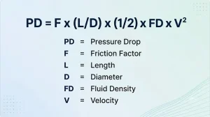
Step 6 — Total Pressure Drop
ΔP = f × (L_total / D) × (ρ × V² / 2)
Step 7 — Friction Rate
Imperial: ΔP_inwg / (L_total_ft / 100) → in.w.g. per 100 ft
Metric: ΔP_Pa / L_total_m → Pa/m
5.Input Parameters Explained
5.1 Airflow (CFM / m³/h)
Airflow is the primary driver of both air velocity and pressure loss. Higher airflow through the same duct diameter means higher velocity, and pressure loss rises roughly with the square of velocity — double the airflow, roughly quadruple the pressure drop.
5.2 Duct Diameter (in / mm)
For rectangular ducts, convert to equivalent hydraulic diameter:
Dh = 2ab / (a + b)
ASHRAE recommends keeping rectangular duct aspect ratios at or below 4:1 to control friction losses.
5.3 Straight Duct Length
The physical length of each straight duct section. Measured from fitting centerline to fitting centerline in practice.
5.4 Equivalent Fitting Length
Fittings don’t just change direction — they create turbulence that adds significant resistance. A single 90° elbow can add 10–30 ft of equivalent straight duct length depending on duct size and bend radius. Always account for fittings; ignoring them is the most common cause of under-pressured HVAC systems.
5.5 Duct Material / Roughness
| Material | Absolute Roughness ε | Typical Use |
|---|---|---|
| Smooth galvanized steel | 0.05–0.10 mm | Commercial HVAC |
| Galvanized steel with joints | 0.15–0.30 mm | Standard sheet metal duct |
| Fiberglass duct board | 0.9 mm | Insulated duct |
| Flexible duct | 0.9–3.0 mm | Branch runs |
| Concrete / masonry | 1.0–3.0 mm | Return air shafts |
6. Fittings & Local Losses
Local losses at fittings are calculated using the loss coefficient method:
ΔP_local = C × VP = C × (ρv² / 2)
| Fitting Type | Loss Coefficient C | Notes |
|---|---|---|
| 90° Round elbow (R/D=1.5) | 0.15–0.22 | Smooth inner wall |
| 90° Rect. elbow with turning vanes | 0.15–0.25 | Recommended for large ducts |
| 90° Rect. elbow without vanes | 1.0–1.3 | Avoid if possible |
| Straight-through tee | 0.01–0.35 | Depends on flow split ratio |
| Branch tee | 0.5–1.8 | Depends on branch angle |
| Gradual expansion (≤15°) | 0.05–0.15 | Smaller angle = less loss |
| Sudden expansion | ∼1.0 | Based on smaller duct VP |
Reference C values should be confirmed against ASHRAE Fundamentals Handbook Chapter 21 for detailed design work.
7. Typical Pressure Drop Ranges
| System Type | Total Pressure Drop | Friction Rate |
|---|---|---|
| Residential | 0.2–0.6 in.w.g. (50–150 Pa) | 0.08–0.15 in.w.g./100ft |
| Light commercial | 0.5–1.0 in.w.g. (125–250 Pa) | 0.10–0.15 in.w.g./100ft |
| Commercial HVAC | 0.8–1.5 in.w.g. (200–375 Pa) | 0.10–0.20 in.w.g./100ft |
| Industrial / high-velocity | 1.0+ in.w.g. (250+ Pa) | 0.20+ in.w.g./100ft |
These ranges are for the complete duct system index run. Fan selection requires adding coil, filter, terminal device, and return duct losses on top of these figures.
8. Step-by-Step Calculation Example
Given (Imperial):
- Airflow: 1,200 CFM
- Duct diameter: 12 in (smooth galvanized, ε = 0.09 mm)
- Straight length: 80 ft
- Equivalent fitting length: 20 ft
Step 1 — Total Effective Length
L_total = 80 + 20 = 100 ft = 30.48 m
Step 2 — Area & Velocity
A = π × (0.3048/2)² = 0.0730 m²
V = 0.5664 ÷ 0.0730 = 7.76 m/s (≈ 1,528 fpm)
Step 3 — Reynolds Number
Re = 7.76 × 0.3048 / 1.516×10⁻⁵ ≈ 156,100
Step 4 — Friction Factor
f ≈ 0.0185
Step 5 — Total Pressure Drop
ΔP = 0.0185 × (30.48 / 0.3048) × (1.2 × 7.76² / 2) ≈ 66.8 Pa (0.27 in.w.g.)
Step 6 — Friction Rate
0.27 in.w.g. per 100 ft
Interpretation: This duct run contributes 66.8 Pa (0.27 in.w.g.) to the system pressure budget. To select the fan, add: cooling coil (0.10–0.30 in.w.g.) + air filter (0.05–0.15 in.w.g.) + supply diffusers + return duct path. A complete system static pressure budget for this airflow typically totals 0.6–0.9 in.w.g.
9. How to Use This Calculator
- Enter airflow — in CFM or m³/h
- Enter duct diameter — in inches or mm
- Enter straight duct length — in ft or m
- Enter equivalent fitting length — total for all fittings in the run
- Select duct material — smooth steel, flex duct, fiberglass, or concrete
- Click Calculate — review total pressure drop, friction rate, and air velocity
- Compare friction rate against your ACCA Manual D or SMACNA target; if above range, increase duct size or reduce run length
10. Engineering Applications
Duct pressure drop calculation is used across a wide range of HVAC engineering tasks:
- Fan and air handler selection — matching equipment static pressure rating to system resistance
- Duct sizing validation — confirming selected duct sizes stay within target friction rate ranges
- Index run identification — finding the highest-resistance path to determine the system design point
- Energy efficiency optimization — reducing oversized fan selection to cut electricity use
- Commissioning troubleshooting — diagnosing airflow shortfalls caused by underestimated duct resistance
11. Common Mistakes to Avoid
| Mistake | Consequence | Correction |
|---|---|---|
| Ignoring fittings entirely | Actual resistance 2–3× calculated | Always add equivalent fitting lengths |
| Using smooth values for flex duct | Friction understated by 3–10× | Select correct roughness (ε ≈ 0.9–3.0 mm) |
| Calculating only one duct segment | Missing system total resistance | Sum all segments along the index run |
| Confusing pressure drop with friction rate | Wrong fan selection or duct sizing | Total pressure drop (Pa) ≠ friction rate (Pa/m) |
| Ignoring altitude / temperature effects | Air density error affects all results | Apply density correction for high-altitude sites |
Design Standards & References
- ASHRAE Fundamentals Handbook — duct design methods, Darcy-Weisbach friction charts, fitting loss coefficients (Chapter 21)
- SMACNA HVAC Duct Design — industry standard for commercial duct construction, pressure loss methods, and leakage classes
- ACCA Manual D — ANSI-recognized residential duct design procedure; uses friction rate and total effective length as primary sizing parameters
12. Limitations of This Calculator
- Assumes standard air density (1.2 kg/m³ at sea level, ~20°C) — no altitude or humidity correction
- Rectangular ducts require conversion to equivalent hydraulic diameter for approximate results
- Does not model duct leakage, acoustic performance, or branch balancing
- Fan curve matching and system curve analysis require additional tools
- ASHRAE and SMACNA both note that total system performance depends on more than single-segment calculations
13. FAQ
Duct pressure drop is the loss of static pressure as air flows through a duct run, caused by wall friction and turbulence at fittings. It is the resistance the fan must overcome to deliver the design airflow.
Use the Darcy-Weisbach equation: ΔP = f × (L/D) × (ρV²/2). Determine friction factor using the Swamee-Jain approximation based on Reynolds number and duct surface roughness, then add local losses for all fittings using loss coefficients.
Flexible duct has a corrugated inner surface with absolute roughness of 0.9–3.0 mm, compared to 0.05–0.10 mm for smooth galvanized steel. Combined with sag and bends from installation, pressure drop can be 3–10 times higher than the same size rigid duct.
Residential systems typically run 0.2–0.6 in.w.g. total; commercial systems 0.5–1.5 in.w.g. The friction rate target for Manual D residential sizing is generally 0.08–0.15 in.w.g. per 100 ft.
The fan must deliver the design airflow against total external static pressure — duct pressure drop plus coil, filter, and terminal losses. Underestimate pressure drop and the fan can’t deliver enough air; overestimate it and you’ll oversize the fan, wasting energy and increasing noise.
14. Conclusion
Duct pressure drop is not a detail to estimate loosely — it is the foundation of every fan selection, every duct sizing decision, and every airflow balance calculation in an HVAC system.
Use this calculator as your first-pass tool to quickly size duct runs, identify over-restrictive paths, and build your static pressure budget before finalizing equipment selection. Then validate with a full system analysis against ASHRAE, SMACNA, and ACCA Manual D standards.
Accurate pressure drop calculation is what separates a system that performs from one that gets called back.