1. Introduction
In more than two decades of building duct-fabrication equipment for contractors in over 100 countries, we have seen the same pattern repeat itself: an HVAC system underperforms not because the chiller, air handler, or rooftop unit was undersized, but because the ductwork was treated as an afterthought. The equipment can be perfect on paper, yet rooms still run hot and cold, energy bills climb, and occupants complain about noise — all because the air never moved the way the design intended.
The duct system is the vascular network of an HVAC installation. It carries conditioned air from the air handling unit to every diffuser, returns stale air for reprocessing, and manages outdoor and exhaust air to hold indoor air quality and pressure. Because most of it is hidden above the ceiling, its complexity is routinely underestimated. But a duct system that is designed and fabricated well is what separates a quiet, balanced, energy-efficient building from one plagued by hot and cold spots, high static pressure, excessive fan energy, and callbacks.
This guide walks through the complete path — from converting loads into airflow, through the three classic sizing methods, pressure-loss and index-run analysis, noise control, insulation, and leakage, all the way to how the design is actually manufactured. That last step is where most articles stop and where real project profitability is won or lost.
2. What Good HVAC Duct Design Actually Delivers
Before methods and formulas, it helps to agree on what “good” means. A well-designed duct system has to satisfy four targets at the same time — and weakness in any one of them undermines the others.
| Performance target | What it means in practice |
|---|---|
| Airflow balance | Every zone receives its design CFM — not just the total airflow being correct |
| Low pressure loss | Lower fan static pressure, lower motor power, lower running cost |
| Acoustic comfort | Air velocity and fittings kept within limits so the system stays quiet |
| Constructability | Duct shapes, seams, flanges and fittings can be fabricated and installed consistently |
Most design guides cover the first three. The fourth — constructability — is where the design meets the shop floor, and it is the target most often ignored. A design that cannot be fabricated cleanly leads to leaky seams, misfit fittings, field rework, and lost margin. We will come back to this in detail.
3. The HVAC Duct Design Workflow, Step by Step
A reliable duct design follows a clear sequence. Skip a step, and the error propagates downstream.
- Calculate zone loads (Manual J / block-load methods)
- Convert loads into required airflow
- Select layout, duct shape and material
- Choose a duct sizing method
- Calculate friction and fitting losses
- Identify the index run and select the fan
- Control noise, insulation, leakage and fire safety
- Fabricate, install, test and balance
The rest of this guide follows this order.
Step 1 — Convert Cooling and Heating Loads Into Airflow
You cannot size a single duct until you know how much air each room actually needs. Airflow is not read off the equipment tonnage — it is derived from each zone’s peak sensible load and the design supply-air temperature difference.
The governing relationship is the sensible-heat equation, which links a room’s sensible load to the mass (and then volume) flow of air required to offset it:
Q = ṁ × cₚ × ΔT
where Q is the sensible load, ṁ is the mass flow of supply air, cₚ is the specific heat of air (≈ 1.006 kJ/kg·K for dry air), and ΔT is the difference between room and supply-air temperature. Rearranged, it tells you the airflow each room demands. Keeping ΔT within a sensible range matters: push the supply-air temperature difference too far and you risk drafts, poor mixing, and comfort complaints; keep it too small and duct sizes balloon.
Two disciplines separate reliable designs from guesswork:
- Do it room by room. A correct total airflow does not guarantee each room gets its share. Near-fan zones tend to be over-supplied and far zones starved unless airflow is allocated per room from the start.
- Account for all loads. Peak cooling, peak heating, ventilation/outdoor-air requirements, latent load, and any pressurization or exhaust needs all feed the number that ultimately governs main-trunk capacity and fan selection.
The largest peak load across all zones sets the size of the main trunk and the air handling unit — everything downstream flows from that figure.
Step 2 — Select Duct Shape, Material and Construction Type
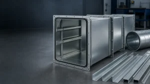
Once you know the airflow, the next decision is how to carry it. Shape and material set the friction, the noise behavior, the cost, and — critically — how the duct will be manufactured.
Round vs. Rectangular vs. Flat-Oval
For a given cross-sectional area, a circle has the smallest perimeter, which means less material, lower friction, higher rigidity, and more uniform airflow. That is why round and spiral duct dominate where efficiency matters. Rectangular duct wins on space adaptability — it fits tight ceilings and building structure — but at equal area it typically carries meaningfully higher friction loss than round duct because of corner boundary-layer effects, and its aspect ratio should be kept moderate (a common rule of thumb is not exceeding about 4:1) before losses climb sharply. Flat-oval duct is the compromise: much of the aerodynamic benefit of round with a lower profile for height-limited spaces.
| Duct type | Advantages | Limitations | Typical use | Fabrication capability needed |
|---|---|---|---|---|
| Round / spiral | Low resistance, high strength, good sealing | Constrained by ceiling height | Long main runs, commercial buildings | Spiral forming / round-duct production |
| Rectangular | Fits structure, space-adaptable | Higher friction at equal area | Height-limited, complex layouts | Auto folding, seam locking, flange forming |
| Flat oval | Low resistance + low height | More complex fittings | Low ceilings needing low pressure loss | Flat-oval forming, custom fittings |
| Flexible | Fast terminal connections | High friction if long/compressed | Short terminal runs only | Not a substitute for main runs |
Material Selection
- Galvanized steel — the mainstream choice; smooth interior, low friction, good value.
- Stainless steel — for corrosive or high-hygiene environments (kitchen exhaust, labs, healthcare).
- Aluminum — light and corrosion-resistant, at higher cost; useful in retrofits sensitive to structural load.
- Fiberglass duct board / composite — built-in insulation and sound absorption for low-velocity runs, but fiber-release concerns limit it in high-IAQ spaces.
- Flexible duct — convenient for short final connections only; keep it short and straight.
The key engineering point: the shape and material you choose here dictate the fabrication process, joint type, sealing approach, and production equipment needed later. A design decision made in five minutes on a drawing determines weeks of shop-floor productivity.
Step 3 — Choose the Right Duct Sizing Method
There are three classic sizing methods. Each has a right place; using the wrong one creates avoidable problems.
1. Equal-Friction Method
Keep a constant friction loss per unit length (Pa/m or in. w.g. per 100 ft) across every duct section, then back-calculate the diameter for each section’s airflow. It is fast, intuitive, and naturally keeps branch losses reasonable, which is why it is the default for most commercial low-velocity systems. Its limitation: it does not guarantee equal pressure at every outlet, so balancing dampers are still needed on larger systems.
Best for: typical commercial HVAC — offices, retail, general low-velocity systems.
2. Velocity-Reduction Method
Start at the fan outlet and step the velocity down as airflow drops after each branch. This gives you direct control over velocity in each section, which is the primary lever for noise. Its limitation: it does not guarantee balanced static pressure, so field balancing with dampers is expected.
Best for: noise-sensitive spaces — libraries, studios, premium offices, hotels.
3. Static-Regain Method
Based on the Bernoulli principle: when you enlarge the downstream duct and velocity falls, some velocity pressure is recovered as static pressure. Sized well, the regain after each branch offsets the friction of the next section, so static pressure stays roughly equal at each takeoff. This is the most theoretically elegant method for large, high-velocity, long-run systems. In practice the static-pressure recovery is only partial and diverging transitions must stay gentle to avoid flow separation, so it reduces balancing effort but does not eliminate field testing and adjustment.
Best for: large, high-velocity systems with long straight main runs.
4. Which method should you use?
| Project condition | Recommended method | Why |
|---|---|---|
| General commercial, normal velocity | Equal friction | Efficient, widely applicable |
| Noise-sensitive space | Velocity reduction | Direct velocity control |
| Large, long-run main system | Static regain | Better static-pressure distribution |
| Industrial / high-static or dust-laden | Calculate separately | Comfort-HVAC parameters do not transfer |
Step 4 — Calculate Pressure Loss and Find the Index Run
Total duct pressure loss = friction loss (straight runs) + dynamic loss (fittings). Getting this right is what determines fan selection and running energy.
1. Friction loss in straight runs
Friction depends on velocity, diameter, length, cross-section, and wall roughness. It is described by the Darcy-Weisbach relationship, in which pressure loss rises with the square of velocity — a crucial fact, because it means over-pushing air through undersized duct is punished heavily and shows up directly as higher fan power.
2. Dynamic loss from fittings
Every elbow, tee, transition, damper, diffuser, filter and coil adds a dynamic loss, expressed through a loss coefficient (C) applied to the velocity pressure. The differences are large and controllable:
- A sharp, un-vaned 90° rectangular elbow has a high loss coefficient.
- Adding turning vanes cuts it substantially.
- A long-radius elbow (R/D ≥ ~1.5) is the lowest-loss configuration of all.
In tightly packed ceiling runs, fitting losses frequently exceed the friction of the straight duct — so fitting selection is not a detail, it is a primary design lever.
3. The index run sets fan static pressure
The index run is the most restrictive path from the fan to the farthest, highest-resistance outlet. Sum the friction and fitting losses along that path — including filters, coils, dampers, silencers and the terminal device — and that total, plus a safety margin (commonly 10–15%), is your fan design static pressure. Do not size the fan by distance alone; size it by the hardest path.
4. Pressure-loss reduction checklist
- Reduce unnecessary elbows and offsets
- Use long-radius elbows or turning vanes
- Avoid abrupt expansions/contractions
- Keep rectangular aspect ratios moderate
- Limit flex-duct length; never let it compress or kink
- Reserve loss allowance for filter loading and aging
- Match fitting sizes to airflow
- Never use a bigger fan to mask a bad duct design
Step 5 — Design for Balanced Air Distribution
Calculations get you a paper design; distribution is whether the far bedroom actually gets its air.
Layout choice — trunk-and-branch, extended-plenum, and radial layouts each suit different building types and each affects fabrication complexity, space, balancing and cost. Choose the layout that keeps runs short and paths symmetrical where possible.
Branch takeoffs and dampers — take branches off cleanly, avoid pulling air immediately downstream of an elbow or in a turbulent zone, and place manual volume dampers where they can actually be adjusted. Size supply diffusers, registers and return grilles for correct throw and coverage.
Testing, Adjusting and Balancing (TAB) — the drawing is not the final performance. Verify outlet flows with a flow hood, pitot-tube traverse or anemometer against design CFM, balance each branch to target, and document the results as part of project handover. This commissioning step is what turns a good design into a system that performs in every room.
Step 6 — Control Duct Noise Before It Becomes a Complaint
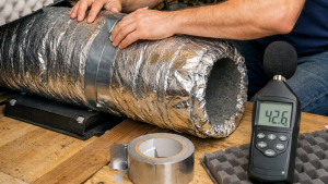
Noise travels the duct from the fan to every diffuser. Its sources are fan-transmitted noise, high-velocity airflow noise, turbulence at elbows/tees/dampers, duct-wall breakout noise, and jet noise at the outlets.
The most important design fact: regenerated airflow noise rises very steeply with velocity — a modest reduction in duct velocity produces a disproportionately large drop in noise. So the fundamental noise-control strategy is simply to keep velocity within limits: lower in main ducts, lower still in branches, lowest at the terminals.
When velocity control alone is not enough, add a silencer (sound attenuator) — but choose it by both insertion loss and added pressure drop, and fold that pressure drop back into your fan static-pressure budget. A silencer that cures noise while quietly adding static pressure has only moved the problem.
Step 7 — Insulation, Leakage Control and Fire Safety
Insulation — supply air is well below ceiling-space temperature, so uninsulated duct loses capacity and risks condensation. Insulate supply runs and any duct in unconditioned space, and include a vapor barrier to keep moisture out of the insulation.
Leakage — the hidden energy drain — leaky seams and joints break balance and waste fan energy. High-static systems especially need attention to seal class. Flanges, seams, corners, access doors and flexible connections are the high-risk points, and a duct-leakage test should be part of quality acceptance. Tightening seams from typical loose levels to a low leakage rate can recover a significant share of annual fan energy — leakage control is one of the highest-return, lowest-glamour investments in the whole system.
Fire and smoke — where duct penetrates fire or smoke barriers, fire dampers, smoke dampers or combination dampers are required. The specific ratings, temperatures and requirements are governed by the codes and standards of the project’s jurisdiction — always design to the local code rather than a generic figure.
Step 8 — Design for Efficient Duct Fabrication and Installation
This is where a duct design becomes a physical product — and where most HVAC content goes silent. It is also where contractor profitability is actually decided.
Why fabrication quality affects HVAC performance
Irregular bends, poor seam locking, uneven flanges and out-of-tolerance fittings translate directly into leakage, difficult assembly, added resistance and field rework. Standardized, machine-made duct is more airtight, faster to install, and dimensionally consistent — which is exactly what your pressure-loss and balancing calculations assumed. When design and fabrication capability are disconnected, the shop produces too many non-standard pieces by hand, and rework erodes margin.
From layout to fabrication operations
A modern duct shop turns the design into product through a defined chain:
- Import CAD/CAM data
- Sheet unfolding and cutting
- Seam locking and stiffening (beading)
- Folding and forming
- Flange or connector forming
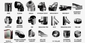
- Elbows, tees, transitions and custom fittings
- Sealing, inspection and packing
- Site installation and commissioning
The tighter this chain, the lower the cost per meter of finished duct and the more predictable the quality.
Duct-fabrication equipment selection guide
Choose equipment by production need, not by model number:
| Production need | Equipment capability | Value to you |
|---|---|---|
| High-volume rectangular duct | Automatic cut, lock, fold line | Higher output, consistent sizing |
| Complex / custom fittings | CNC cutting, folding, forming | Accuracy on difficult parts |
| Flange connections | Integral / TDF flange forming | Faster assembly, sealed joints |
| Long straight duct runs | Automated production line | Less labor dependence, fewer errors |
| Higher sealing / QC demands | Stable forming, stiffening, inspection | Supports low leakage and acceptance |
Selecting the right line starts with your duct type, production volume, joint system, material thickness, and automation target.
4. Common HVAC Duct Design Mistakes — and How to Avoid Them
| Common mistake | Consequence | Fix |
|---|---|---|
| Sizing by total airflow only | Uneven room airflow | Allocate airflow room by room |
| Bigger fan to fight a bad layout | Higher energy, noise, cost | Optimize path, fittings, sizing first |
| Overusing flex duct | Higher friction, lower CFM | Short, straight terminal runs only |
| Ignoring fitting losses | Real static far above design | Sum elbow/tee/damper/equipment losses |
| No balancing dampers | Cannot fine-tune later | Add adjustable devices on key branches |
| Ignoring leakage | Lost airflow and energy | Specify seal class and leakage testing |
| Designing without fabrication in mind | Non-standard parts, rework | Review manufacturability and equipment early |
| Chasing pressure loss, ignoring noise | Poor comfort | Control velocity, fittings and silencing together |
5.FAQ
Keep runs short and straight, use an adequate diameter to hold velocity moderate, swap sharp elbows for long-radius elbows or turning vanes, use gradual transitions, choose smooth material, and limit flexible duct. Each fix compounds.
Yes. They guide air around a rectangular elbow instead of letting it separate off the outer wall, cutting both the elbow’s loss coefficient and its noise — the best fix where a long-radius elbow won’t fit.
Keep branch takeoffs at least about two feet from the fan outlet, elbows and other takeoffs, so turbulent air has room to redevelop first. This lowers turbulence and pressure loss and balances airflow to each branch.
Neither extreme is ideal, but slight oversizing is the safer error — undersizing spikes velocity, pressure loss, energy and noise. The real goal is sizing to the correct design velocity and friction rate, not simply “big” or “small.”
Keep main velocity moderate (~4–6 m/s), reduce it toward the branches, hold rectangular aspect ratios to about 4:1 or less, and target a friction rate near 0.8–1.2 Pa/m. Treat these as a sanity check, not a replacement for real load-based sizing.
Up to a point, yes — upsizing an undersized duct cuts friction and lets the fan push more CFM. But past the point where velocity is already adequate, further enlargement adds little and eventually harms distribution.
6. Conclusion
Great HVAC duct design is only half the job — the other half is fabricating it accurately, airtight, and at scale. With 20+ years of experience and equipment serving contractors in over 100 countries, Durmapress® helps you match the right duct-fabrication line to your duct type, volume and quality targets.
Tell us your duct type and production goals, and our engineers will recommend a fabrication solution — with a free quote and product brochure within 24 hours.